Method and system for vacuum generation
A vacuum and vacuum container technology, applied in the direction of charging system, pump/compressor arrangement, electrical control, etc., can solve the problem of not being able to use the ejector to complete the vacuum
- Summary
- Abstract
- Description
- Claims
- Application Information
AI Technical Summary
Problems solved by technology
Method used
Image

Examples
Embodiment Construction
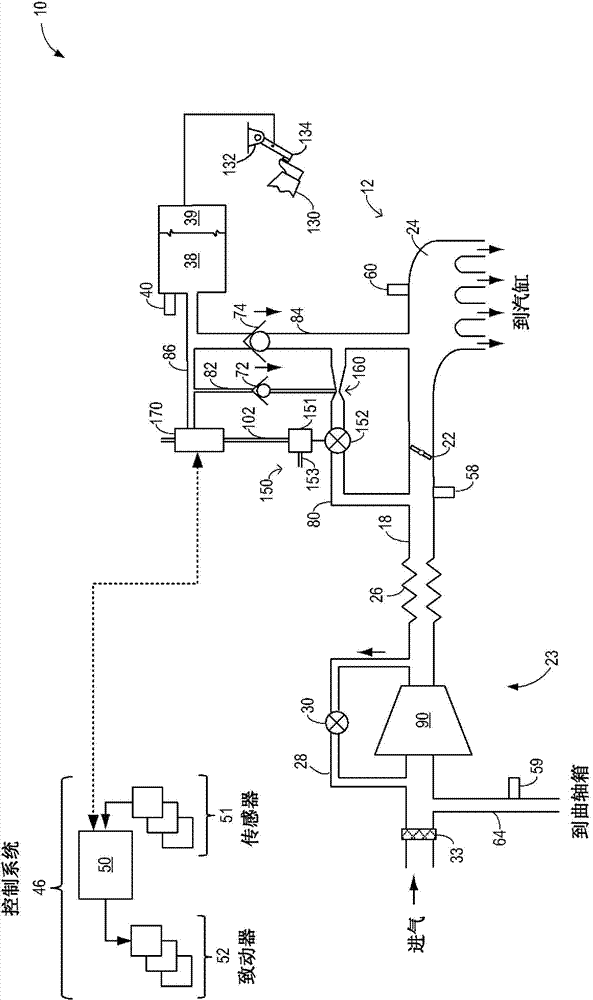
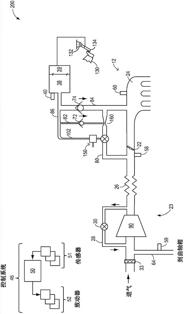
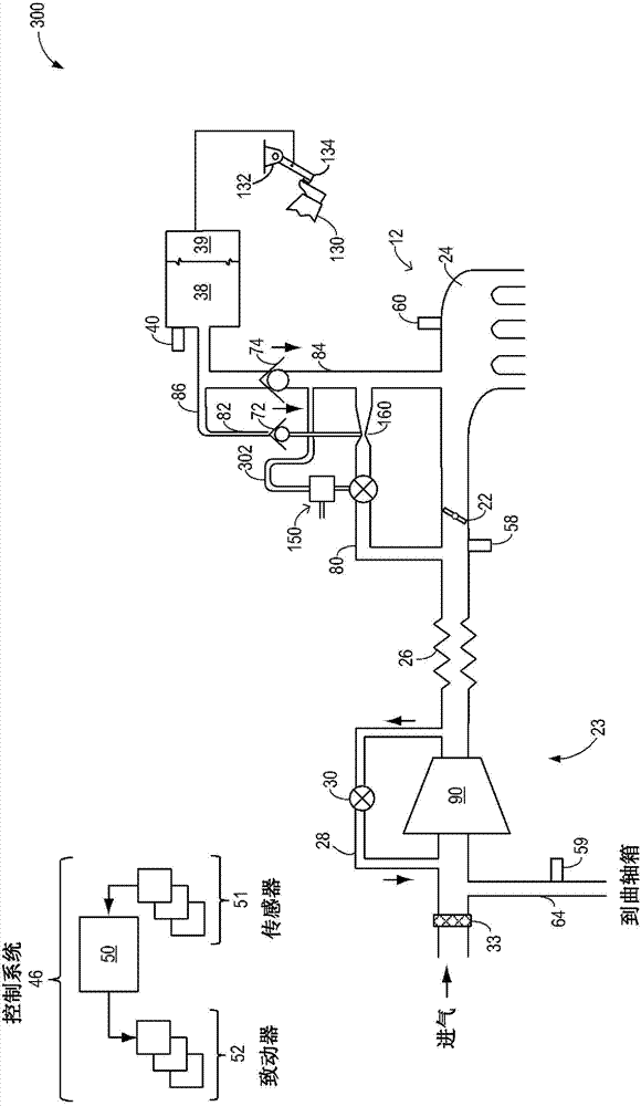
[0018] The present invention provides for low-cost control by being coupled to an engine system such as Figure 1-5 with Figure 7 Method and system for power flow of an injector for an engine system. Motive flow valves can be coupled to injectors such as Figure 1-5 shown in . The valve may be pneumatically controlled and vacuum actuated so that motive flow through the valved injector can be appropriately increased or decreased ( Image 6 ). In some embodiments, such as Figure 7 As shown in , a vacuum-actuated throttle can be used to control power flow through the injector. By coupling a vacuum actuated valve (or throttle) to a vacuum reservoir of the engine system, the valve can be actuated to open or close based on vacuum replenishment requirements. The controller can be configured to execute control programs such as Figure 8 example program) so that the valve opens to increase motive flow (and vacuum generation) at the ejector when vacuum availability at the vesse...
PUM
 Abstract
Description
Claims
Application Information