
Method and system for vacuum generation

A vacuum and vacuum container technology, applied in the charging system, pump/compressor arrangement, electrical control, etc., can solve the problem of not being able to use the ejector to completely vacuum and so on

Active Publication Date: 2018-09-18
FORD GLOBAL TECH LLC
View PDF6 Cites 0 Cited by
  • Summary
  • Abstract
  • Description
  • Claims
  • Application Information

AI Technical Summary

Problems solved by technology

Therefore, without controlling the air flow through the ejector, the full vacuum generation potential of the ejector cannot be exploited

Method used


Image

  • Method and system for vacuum generation
  • Method and system for vacuum generation
  • Method and system for vacuum generation

Examples


Embodiment Construction

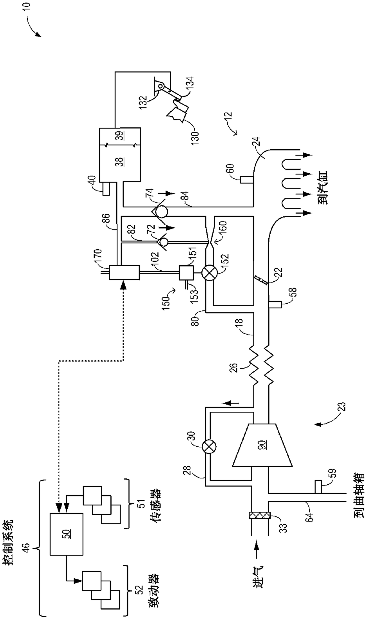
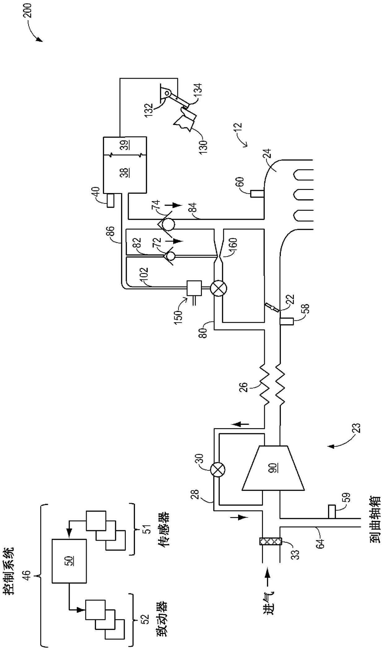
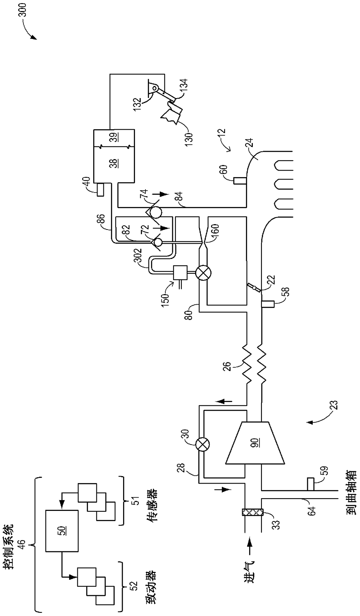
[0018] The present invention provides for low-cost control by being coupled to an engine system such as Figure 1-5 and Figure 7 Method and system for power flow of an injector for an engine system. Motive flow valves can be coupled to injectors such as Figure 1-5 shown in . The valve may be pneumatically controlled and vacuum actuated so that motive flow through the valved injector can be appropriately increased or decreased ( Figure 6 ). In some embodiments, such as Figure 7 As shown in , a vacuum-actuated throttle can be used to control power flow through the injector. By coupling a vacuum actuated valve (or throttle) to a vacuum reservoir of the engine system, the valve can be actuated to open or close based on vacuum replenishment requirements. The controller can be configured to execute control programs such as Figure 8 example program) so that the valve opens to increase motive flow (and vacuum generation) at the ejector when vacuum availability at the vesse...


PUM


Abstract

Methods and systems are provided for controlling motive flow through an ejector using a pneumatically controlled valve. A vacuum actuated valve may be opened at low vacuum conditions to increase motive flow through the ejector while the valve is closed at high vacuum conditions to decrease the motive flow. This allows motive flow through the ejector to be controlled based on vacuum needs at low component cost.

Description

[0001] Cross References to Related Applications [0002] This application claims the benefit of and priority to US Provisional Patent Application 61 / 737,004, filed December 13, 2012, the contents of which are hereby incorporated by reference for all purposes. technical field [0003] The present invention relates to improving the vacuum generation efficiency of an ejector coupled to an engine system. Background technique [0004] Vehicle systems may include various vacuum consumers that utilize vacuum actuation. These devices may include, for example, brake boosters. The vacuum used by these devices can be provided by a dedicated vacuum pump. In other embodiments, one or more injectors can be coupled in an engine system that can manage engine airflow and use it to create vacuum. [0005] Thus, the amount of vacuum created at the ejector can be controlled by controlling the motive air flow rate through the ejector. In one example, this can be accomplished by using a large...

Claims


Application Information

Patent Timeline
Patent Type & Authority Patents(China)
IPC IPC(8): F02D45/00
CPCB60T13/46B60T17/02F02D23/00F02D41/0002F02D2250/41F02M25/06Y02T10/12Y02T10/40F02D41/0007
Inventor R·D·普斯夫
Owner FORD GLOBAL TECH LLC
Learn More