Ratio shift control system for an automatic transmission

A technology of automatic transmission and control system, applied in transmission control, control device, components with teeth, etc., can solve problems such as difficult and high-quality drive control, and achieve effective high-quality drive control, effective drive control, high-quality The effect of drive control

Inactive Publication Date: 2014-01-15
SUZUKI MOTOR CO LTD
View PDF5 Cites 2 Cited by
  • Summary
  • Abstract
  • Description
  • Claims
  • Application Information

AI Technical Summary

Problems solved by technology

This makes it difficult to expect effective high-quality drive control

Method used


Image

  • Ratio shift control system for an automatic transmission
  • Ratio shift control system for an automatic transmission
  • Ratio shift control system for an automatic transmission

Examples


Embodiment Construction

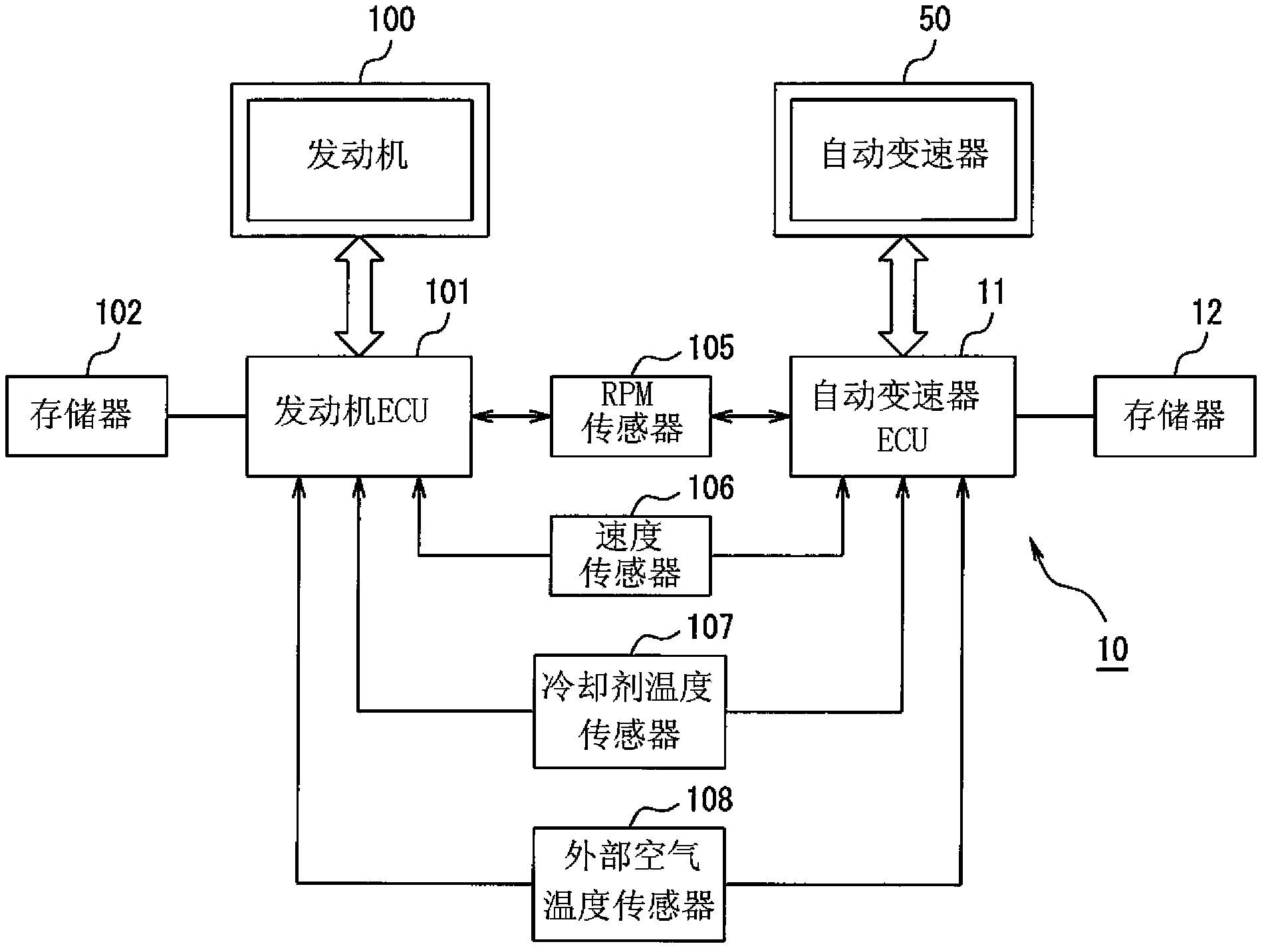
[0020] Hereinafter, embodiments of the present invention will be described in detail with reference to the accompanying drawings. Figure 1 to Figure 5 is a view showing one embodiment of a shift control system for an automatic transmission according to the present invention.

[0021] refer to figure 1 , the transmission control system 10 is configured to control the operation of an automatic transmission installed in a motor vehicle together with an engine (or an internal combustion engine) operated by gasoline. The automatic transmission is configured to automatically shift to one of a plurality of gear ratios between the rotational input speed and the output speed of the output shaft of the engine to deliver shaft torque of the engine to the automatic transmission for propelling traction wheels Turn the shaft on the outer side to enable movement of the vehicle.

[0022] Currently, the engine introduces pressurized gasoline with air into the combustion chamber in the cylin...


PUM


Abstract

A ratio shift control system for an automatic transmission calculates the magnitude of a difference in temperature between a detected engine coolant temperature and a detected outside air temperature, which are detected by coolant and outside air temperature sensors, respectively, during one engine start of an internal combustion engine. Ratio shift in the automatic transmission is controlled based on the detected outside air temperature during the one engine start when the magnitude of the difference in temperature is equal to or less than a predetermined cold engine evaluation threshold.

Description

technical field [0001] The present invention relates to a shift control system for an automatic transmission, and more particularly, to a shift control system for controlling an automatic shift by obtaining an appropriate outside air temperature. Background technique [0002] Motor vehicles have been driven efficiently by on-board automatic transmissions, which transmit the shaft torque of the internal combustion engine (or "engine") to its output side, pushing the traction wheels, while regulating the number of revolutions to the appropriate . In order to provide efficient power transmission, it is necessary to adjust the control conditions according to the outside air temperature and the like, so this type of automatic transmission uses the detected temperature from the outside air temperature sensor. [0003] It is known practice to arrange such an outside air temperature sensor in the engine compartment. Thus, the outside air temperature sensor is affected by the radia...

Claims


Application Information

Patent Timeline
IPC IPC(8): F16H61/02F16H59/78F16H59/64
CPCB60W10/06B60W10/11B60W30/194B60W2510/0676B60W2555/20F16H59/64F16H61/0213F16H59/78F16H2061/0232
Inventor 小泉槙吾吉田谕广
Owner SUZUKI MOTOR CO LTD
Why Eureka
Try Eureka