Vertical cabinet type air-conditioner

An air conditioner and vertical cabinet technology, which is applied in the field of air conditioners, can solve the problems of narrowing the air supply angle range, weak wind, and difficulty in directing the wind direction to the front, so as to increase the air supply angle, improve comfort, and improve comfort. Effect

Active Publication Date: 2014-01-15
GREE ELECTRIC APPLIANCES INC
View PDF8 Cites 12 Cited by
  • Summary
  • Abstract
  • Description
  • Claims
  • Application Information

AI Technical Summary

Problems solved by technology

[0003] For traditional cabinets with air outlet from the front, the upper and lower sweeping blade assemblies and the left and right sweeping blade assemblies need to be installed at the air outlet. Usually, in order to let the cold air fall to the ground as much as possible in the cooling mode, it is necessary to make the upper and lower sweeping blades The components are arranged on the outside of the tuyere, and the left and right sweeping blade assemblies are arranged on the inside of the tuyere, so that the setting position of the left and right sweeping blade assemblies is too deep, which will cause the left and right sweeping blades near the edges of the left and right tuyere to blow to the left or right If the wind is blocked by the air outlet, the left and right sweeping effect will be weakened, resulting in a narrow range of left and right air supply angles of the whole machine, and the comfort effect is not ideal
[0004] In contrast to the traditional cabinets with side air outlets, since the air outlets are set on the left and right sides, the air supply angle is generally biased to the left and right sides, and it is difficult to guide the air direction to the front.
Or because of the appearance factor, the air outlet should not be opened too wide. In this way, the frontal projection area of ​​the air outlet is very small. Even if the wind direction can be directed to the front, the wind blowing out is also very weak, and the comfort effect is also not ideal.

Method used


Image

  • Vertical cabinet type air-conditioner
  • Vertical cabinet type air-conditioner
  • Vertical cabinet type air-conditioner

Examples


Embodiment Construction

[0024] The present invention will be described in detail below with reference to the accompanying drawings and examples. It should be noted that, in the case of no conflict, the following embodiments and features in the embodiments can be combined with each other.

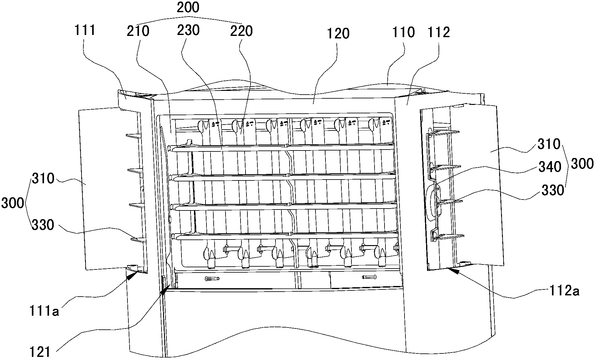
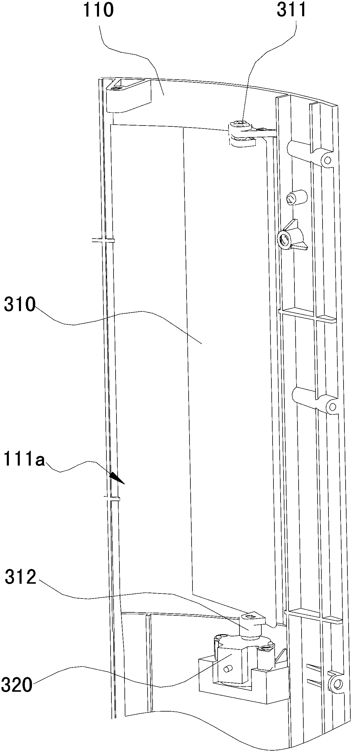
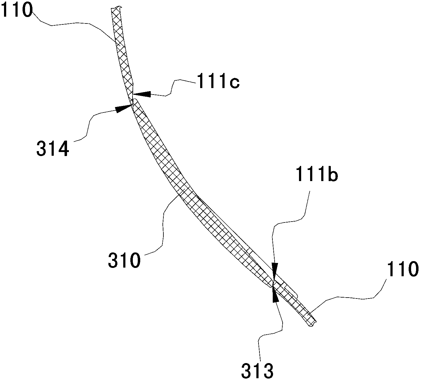
[0025] The structure of the vertical cabinet air conditioner in one of the embodiments of the present invention is as follows: figure 1 As shown, a front air outlet 121 and a side air outlet 111a are respectively provided on the front and side of the casing 100, and front air guides for guiding the front air outlet are respectively provided at the front air outlet 121 and the side air outlet 111a. The component 200 and the side air guiding component 300 for guiding the side air. In this embodiment, the casing 100 includes a casing 110 and an air outlet panel 120, the front air outlet 121 is arranged on the upper part of the air outlet panel 120, and the side air outlet 111a is arranged on the left side panel 111 a...


PUM


Abstract

The invention discloses a vertical cabinet type air-conditioner which comprises a machine shell. A front face air outlet is formed in the front face of the machine shell. A front face air guiding assembly used for guiding front face air outlet is arranged at the front face air outlet. A side face air outlet is formed in the side face of the machine shell. A side face air guiding assembly used for guiding side face air outlet is arranged at the side face air outlet. The side face air guiding assembly comprises a side air guiding plate and one or more side air guiding plates, wherein the side air guide plate can rotate around the vertical axis and is used for opening and closing the side face air outlet, and the one or more air guide blades are arranged on the inner side of the side air guiding plate and can rotate around the transverse axis. The vertical cabinet type air-conditioner simultaneously comprises the front face air guiding assembly and the side face air guiding assembly, utilizes the side air guide plate of the side face air guiding assembly to guide the lateral direction of air, and utilizes the side air guiding blades of the side face air guiding assembly to guide the vertical direction of air. Consequently, the air supply angle of the whole machine can be increased, and the utilization comfort of the air-conditioner is effectively improved.

Description

technical field [0001] The invention relates to an air conditioner, in particular to a vertical cabinet type air conditioner. Background technique [0002] With the development of science and technology, the appearance and appearance of vertical cabinet air conditioners are various, but the air outlet method is relatively simple. Usually, an opening is used at the position of the front air outlet panel to achieve the effect of front air outlet; A strip-shaped hole is opened on each of the two sides to achieve the effect of side wind. [0003] For traditional cabinets with air outlet from the front, since the upper and lower sweeping blade assemblies and the left and right sweeping blade assemblies need to be installed at the air outlet position, usually in order to let the cold air fall to the ground as much as possible in the cooling mode, it is necessary to make the upper and lower sweeping blades The components are arranged on the outside of the tuyere, and the left and ...

Claims


Application Information

Patent Timeline
Patent Type & Authority Applications(China)
IPC IPC(8): F24F1/00F24F13/14
Inventor 尚彬古汤汤吴庆壮曾友坚
Owner GREE ELECTRIC APPLIANCES INC
Why Eureka
Try Eureka