A three-mirror compact field antenna measurement system

A technology of antenna measurement and three mirrors, which is applied in the direction of electromagnetic field characteristics, can solve problems such as high manufacturing costs, and achieve the effects of eliminating fluctuations, improving the quality of the quiet zone, and excellent low-quiet zone amplitude and phase fluctuations

Active Publication Date: 2016-01-20
北京航天元培教育科技有限公司
View PDF1 Cites 0 Cited by
  • Summary
  • Abstract
  • Description
  • Claims
  • Application Information

AI Technical Summary

Problems solved by technology

The dual-mirror system requires two large-aperture mirrors, and the manufacturing cost is high

Method used


Image

  • A three-mirror compact field antenna measurement system
  • A three-mirror compact field antenna measurement system
  • A three-mirror compact field antenna measurement system

Examples


Embodiment Construction

[0030] In order to make the object, technical solution and advantages of the present invention clearer, the present invention will be further described in detail below with reference to the accompanying drawings and examples.

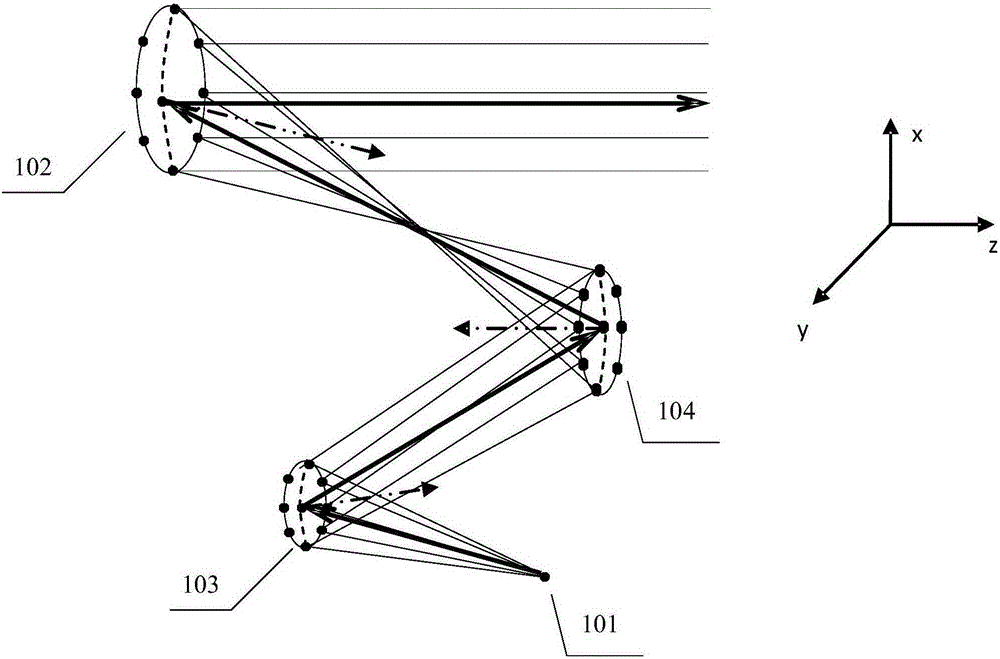
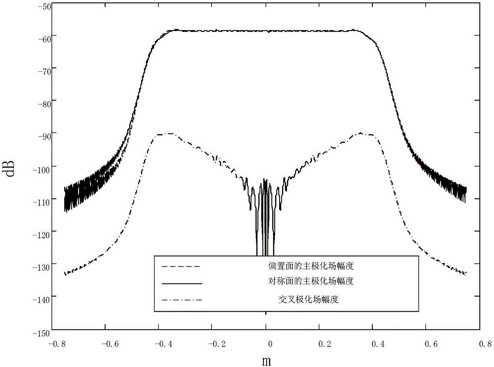
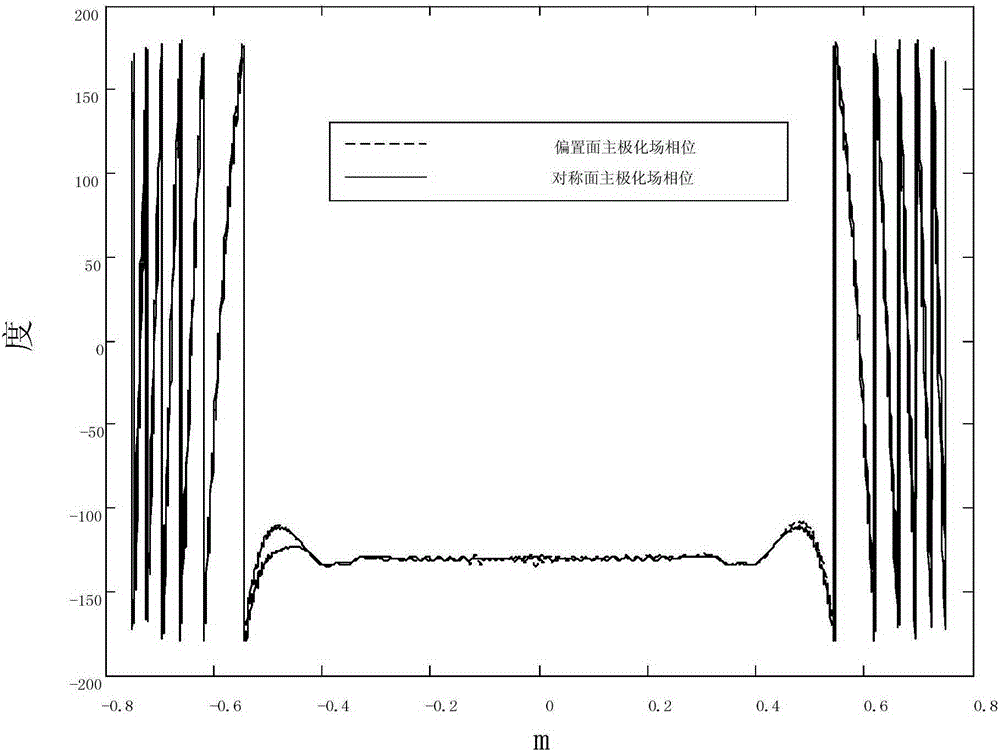
[0031] In the present invention, a three-mirror compact-field antenna measurement system is provided, which uses Cassegrain-Gregorian, Gregory-Cassegrain, or Cassegrain-Cassegrain three-reflection The compact field antenna measurement system is designed by using the mirror structure, which can not only obtain high cross-polarization isolation, but also obtain excellent low-quiet-zone amplitude and phase fluctuations.

[0032] figure 1 It is a structural schematic diagram of the three-mirror compact field antenna measurement system of the present invention. Such as figure 1 As shown, a three-mirror compact field antenna measurement system provided by the present invention includes a feed source 101, a primary reflector 102 with a definite shape, and tw...


PUM


Abstract

The invention provides a three-reflector compact field antenna measuring system. The three-reflector compact field antenna measuring system comprises a feed source, a primary reflector, a first shaping secondary reflector and a second shaping secondary reflector, wherein electromagnetic waves sent by the feed source are reflected to the second shaping secondary reflector through the first shaping secondary reflector, the electromagnetic waves are reflected to the primary reflector through the second shaping secondary reflector, the electromagnetic waves reflected by the primary reflector outgo as plane electromagnetic waves, and a system outgoing field is generated; the first shaping secondary reflector and the second shaping secondary reflector form a Cassegrain antenna structure, and the second shaping secondary reflector and the primary reflector form a Gregory antenna structure. According to the three-reflector compact field antenna measuring system, the Cassegrain-Gregory three-reflector structure is adopted to design the compact field antenna measuring system, a high primary reflector caliber using rate can be achieved, good silent area performance is kept, and manufacturing cost is lowered.

Description

technical field [0001] The invention relates to the technical field of millimeter wave and submillimeter wave quasi-light, in particular to a three-mirror compact field antenna measurement system. Background technique [0002] In the field of civil aerospace, millimeter wave and submillimeter wave technologies have broad application prospects. In atmospheric observation, the use of millimeter wave and submillimeter wave technology can detect gases such as water vapor, oxygen, carbon dioxide, and ozone, thereby inverting the corresponding climate change; in deep space exploration, the use of millimeter wave and submillimeter wave technology can Detect cosmic rays to study the evolution of galaxies in the universe. [0003] In order to guarantee the working quality of millimeter-wave and submillimeter-wave systems, they must be accurately measured. But measuring antenna systems in the mmWave and submillimeter bands is a general challenge. In the compact field mirror antenna...

Claims


Application Information

Patent Timeline
Patent Type & Authority Patents(China)
IPC IPC(8): G01R29/08
Inventor 俞俊生杨诚陈晓东姚远刘小明晁永辉陆泽健
Owner 北京航天元培教育科技有限公司
Why Eureka
Try Eureka