
A three-mirror compact field antenna measurement system and method for determining its structure and parameters

A technology of antenna measurement and three-mirror, which is applied in the direction of measuring devices, antenna radiation patterns, and measuring electrical variables, etc., which can solve the problems of increased construction cost and assembly difficulty, low degree of freedom in geometric design, and large focal diameter of the main reflector.

Active Publication Date: 2022-07-29
BEIJING UNIV OF POSTS & TELECOMM
View PDF12 Cites 0 Cited by
  • Summary
  • Abstract
  • Description
  • Claims
  • Application Information

AI Technical Summary

Problems solved by technology

In the current three-mirror compact field antenna measurement system, in order to obtain better quiet zone performance, the direction of the feed source is relatively fixed and cannot be flexibly changed according to actual needs. At the same time, the geometric relationship between the three mirrors is also relatively fixed , and the focal diameter of the main reflector is large, resulting in a large lateral dimension of the entire system, which increases the construction cost and assembly difficulty of the entire system, and the geometric design freedom of the entire system is low

Method used


Image

  • A three-mirror compact field antenna measurement system and method for determining its structure and parameters
  • A three-mirror compact field antenna measurement system and method for determining its structure and parameters
  • A three-mirror compact field antenna measurement system and method for determining its structure and parameters

Examples


Embodiment Construction

[0041] The technical solutions in the embodiments of the present invention will be clearly and completely described below with reference to the accompanying drawings in the embodiments of the present invention. Obviously, the described embodiments are only a part of the embodiments of the present invention, but not all of the embodiments. Based on the embodiments of the present invention, all other embodiments obtained by those of ordinary skill in the art based on the present application fall within the protection scope of the present invention.

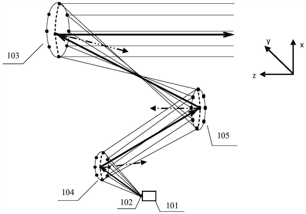
[0042]In order to improve the geometric design freedom of the antenna measurement system, the embodiment of the present invention provides a three-mirror compact field antenna measurement system, and a structure and parameter determination method of the three-mirror compact field antenna measurement system. The following first describes the embodiments of the present invention. The supplied three-mirror compact field antenna measurem...


PUM


Abstract

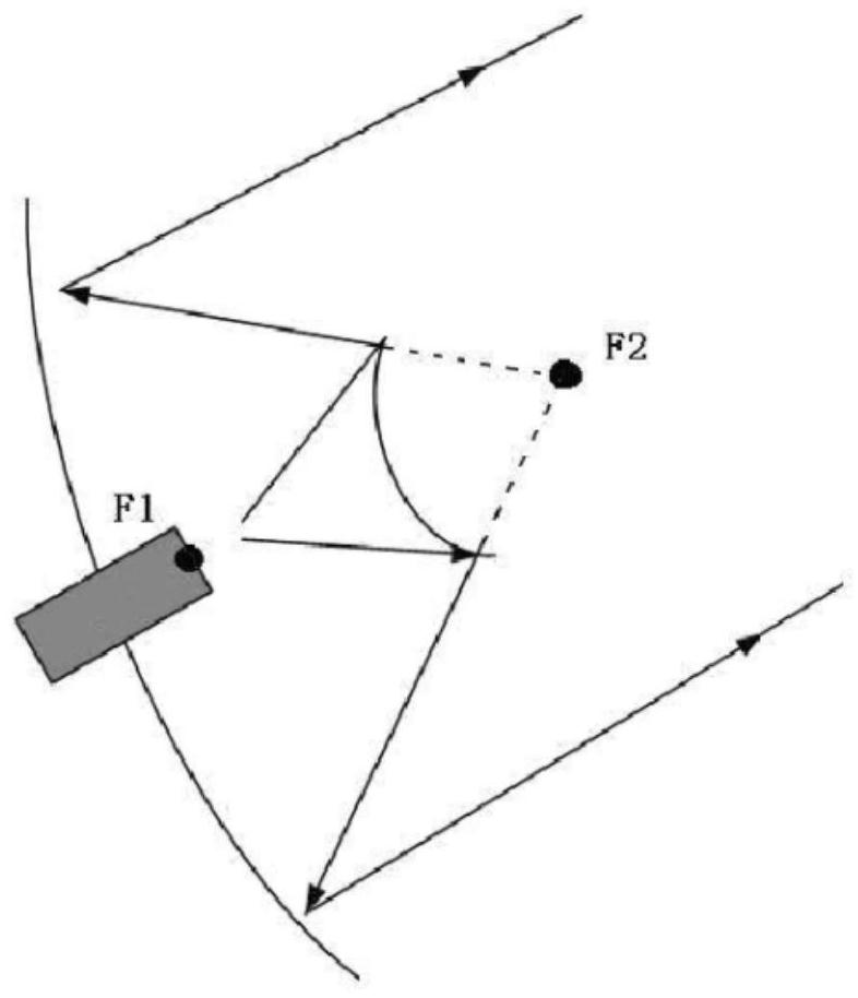
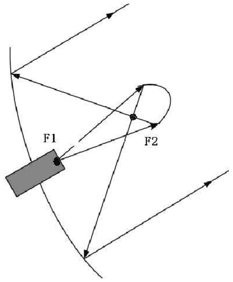
Embodiments of the present invention provide a three-mirror constricted field antenna measurement system and a method for determining its structure and parameters. In the system, the feed source is set on a direction moving device, the size and curvature of the main mirror are fixed, and the two shaping pairs are fixed. The reflectors are all shaped reflectors with adjustable concavity and convexity. The parameters and the geometric relationship between the reflectors are determined based on the equivalent paraboloid theory and the beam mode expansion theory. The electromagnetic wave emitted by the feed is reflected by the first shaped sub-reflection. The mirror, the second shaping sub-reflector and the main reflector reflect to form an exit field. In the three-reflector compact field antenna measurement system provided by the embodiment of the present invention, the electromagnetic wave radiation direction emitted by the feed can be flexibly adjusted by adjusting the direction moving device, and the parameters of the two shaped sub-reflectors and the geometric positions between the reflectors can be adjusted. The relationship can be calculated and determined based on the equivalent paraboloid theory and the beam mode expansion theory, so that the three-mirror compact field antenna measurement system has a high degree of freedom in geometric design.

Description

technical field [0001] The invention relates to the technical field of antenna measurement, in particular to a three-mirror compact field antenna measurement system and a structure and parameter determination method of the three-mirror compact field antenna measurement system. Background technique [0002] Millimeter-wave terahertz technology has a wide range of applications in astronomy, remote sensing, imaging, security inspection and other fields. In order to ensure that millimeter-wave terahertz technology can work normally, it needs to be accurately measured. In millimeter-wave terahertz technology, large-diameter antennas are usually used, but it is difficult for conventional field method measurements to meet the far-field measurement distance conditions required for large-diameter antenna measurements. Therefore, when measuring millimeter-wave terahertz systems, generally A compact field antenna measurement system is used. [0003] The compact field antenna measureme...

Claims


Application Information

Patent Timeline
Patent Type & Authority Patents(China)
IPC IPC(8): G01R29/08G01R29/10
CPCG01R29/0885G01R29/0892G01R29/105
Inventor 姚远俞俊生于海洋李峙陈天洋陈雨晴张亮陈晓东
Owner BEIJING UNIV OF POSTS & TELECOMM
Learn More