Supercharge Your Innovation With Domain-Expert AI Agents!

Image display apparatus and method for controlling same

A technology of an image display device and a control method, which is applied in the directions of image communication, image data processing, and 3D image processing, etc., can solve the problem that the stereoscopic effect cannot be adjusted locally.

Inactive Publication Date: 2014-01-15
SEIKO EPSON CORP
View PDF3 Cites 0 Cited by
  • Summary
  • Abstract
  • Description
  • Claims
  • Application Information

AI Technical Summary

Problems solved by technology

[0005] However, although the technology described in Patent Document 2 can adjust the three-dimensionality of the image as a whole by changing the positional relationship between the right-eye image and the left-eye image, it cannot locally adjust the three-dimensionality.

Method used


Image

  • Image display apparatus and method for controlling same
  • Image display apparatus and method for controlling same
  • Image display apparatus and method for controlling same

Examples


no. 1 approach

[0034] Next, an image display system according to a first embodiment will be described with reference to the drawings.

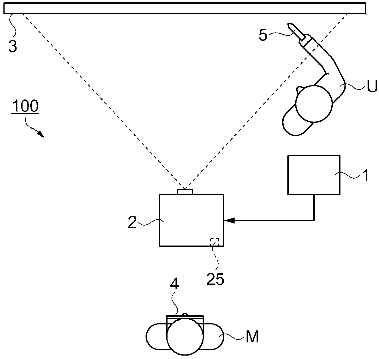
[0035] figure 1 It is a plan view showing a schematic configuration of the image display system of this embodiment.

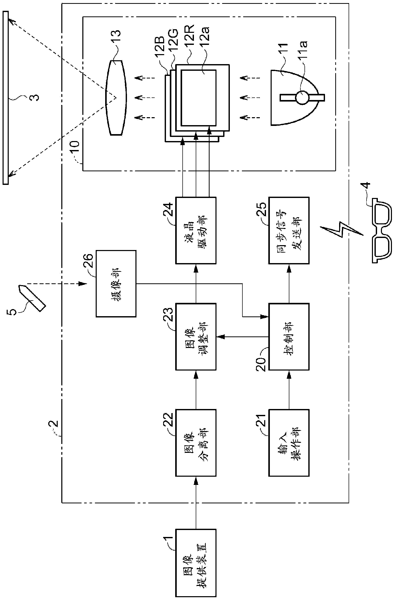
[0036] Such as figure 1 As shown, the image display system 100 is a system that uses binocular parallax to allow the viewer M to recognize a stereoscopic image, and is configured to include: an image providing device 1 that provides image information, a projector 2 as an image display device, and a projector 2 as a device for projecting images. The screen 3 on which the instrument 2 projects, the liquid crystal shutter glasses 4 as a shutter device, and the electronic pen 5.

[0037] The image providing device 1 is a device that provides image information for recognizing a stereoscopic image to the projector 2, and in this embodiment outputs left-eye image information representing an image for the left eye and a right-eye image representing...

no. 2 approach

[0066] Next, an image display system according to a second embodiment will be described with reference to the drawings.

[0067] The configuration of the image display system 100 of the second embodiment is the same as that of the first embodiment, but the operation of the projector 2 is different from that of the first embodiment. The projector 2 of the first embodiment emphasizes the images in the emphasis area E by moving the emphasis area E for the left-eye image and the right-eye image respectively, but the projector 2 of the present embodiment fixes the emphasis area E, The non-emphasized area F outside the emphasized area E is moved.

[0068] Figure 5is an explanatory diagram for explaining the emphasis processing performed by the image adjustment unit 23 of this embodiment, Figure 5 (a) is a diagram showing a projected image before emphasis processing is performed, Figure 5 (b) is a diagram showing an image for the left eye during enhancement processing, Figure...


PUM


Abstract

The invention provides an image display apparatus and a method for controlling the same, which enables a stereoscopic sensation of an image to be partially. When a user instructs a control unit about a position (L) in a substantially central portion of an illustration (G2) with an electronic pen, the control unit determines a rectangular area that surrounds the illustration (G2) as an enhancement area (E). An image adjustment unit carries out a process of shifting the portion in the enhancement area (E) in an image (Pl) for the left eye rightward by a predetermined amount (A1) and shifting the portion in the enhancement area (E) in an image (Pr) for the right eye leftward by a predetermined amount (A2). As a result, the illustration (G2) located in the enhancement area (E) is so changed that the image for the left eye (solid line) is shifted to a position to the right of the image for the right eye (dotted line) and hence recognized as if the illustration were located in front of other illustrations (G1, G3, G4). The illustration (G2) in the enhancement area is thus enhanced.

Description

technical field [0001] The present invention relates to an image display device that allows a viewer to recognize a displayed image as a stereoscopic image and a control method thereof. Background technique [0002] In order for the viewer to recognize the image displayed by an image display device such as a projector as a stereoscopic image, various techniques for making the viewer's left and right eyes recognize mutually different images (parallax images) have been proposed (for example, refer to Patent Document 1). In this technique, the three-dimensionality recognized by the viewer changes according to the amount of parallax between the image for the right eye and the image for the left eye. Patent Document 2 describes a digital broadcast receiver capable of adjusting the amount of parallax by changing the horizontal display positions of a left-eye image and a right-eye image. [0003] Patent Document 1: Japanese Patent Laid-Open No. 2011-257645 [0004] Patent Docume...

Claims


Application Information

Patent Timeline
Patent Type & Authority Applications(China)
IPC IPC(8): G02B27/22H04N13/04G02F1/133G03B35/00
CPCH04N2013/0092H04N13/128G06T19/20G06T15/10G06T15/00G06T19/00G06T17/20G06T17/00
Inventor 升达彦
Owner SEIKO EPSON CORP
Features
  • R&D
  • Intellectual Property
  • Life Sciences
  • Materials
  • Tech Scout
  • Unparalleled Data Quality
  • Higher Quality Content
  • 60% Fewer Hallucinations
Learn More