Rear-die slide block time-lapse core pulling mould structure

A slider and rear mold technology, applied in the field of delayed core-pulling mold structure of the rear mold slider, can solve the problems of easy sticking of the product to the front mold, low mold production efficiency, manpower and time, etc., to achieve rapid demoulding and ensure The effect of production efficiency

Inactive Publication Date: 2014-01-22
VANGUARD TECH WUXI
View PDF0 Cites 2 Cited by
  • Summary
  • Abstract
  • Description
  • Claims
  • Application Information

AI Technical Summary

Problems solved by technology

[0002] Some products have a large upper end surface area, and the side is provided with a concave structure. The existing mold structure drives the side slider to move when the front mold is demoulded. Due to the large contact area between the front mold and the product , and the simultaneous separation of the side slider and the concave structure makes the product easy to stick to the front mold, which in turn requires additional manpower, time and front mold to complete the separation of the product, making the production efficiency of the mold low

Method used


Image

  • Rear-die slide block time-lapse core pulling mould structure

Examples


Embodiment Construction

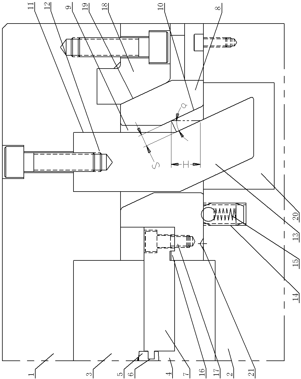
[0011] See figure 1 , which includes A plate 1, B plate 2, front mold 3, and rear mold 4. A cavity is formed between the front mold 3 and the rear mold 4, and the product 5 is inside the cavity, and the side of the product 5 is provided with a concave structure 6, The inner side of the side slider 7 goes deep into the concave structure 6, the outer side of the side slider 7 is fastened to the slider seat 8, the slider seat 8 is supported on the B board 2, and the position of the slider seat 8 away from the side slider is opened. There is a guide groove 9, the outer lower part of the guide groove 9 is a slope 10, the slope 10 is specifically a slope from top to bottom, and its slope is α, the guide groove 9 runs through a guide post 11, and the guide post 11 includes an upper vertical To the part 12, the lower inclined guide part 13, the lower inclined guide part 13 is a structure inclined outward from top to bottom, and its slope is α; the vertical part 12 is fastened to the A...


PUM


Abstract

The invention provides a rear-die slide block time-lapse core pulling mould structure. According to the structure, if the area of an upper end face of a product is large, and a side part is provided with an inner concave structure, a mould front die, a side slide block and the product are separated without occurring of the phenomenon of sticking the front die, and demoulding is quick to ensure the production efficiency of a mould. The rear-die slide block time-lapse core pulling mould structure comprises an A board, a B board, the front die and a rear die, a mould cavity is formed between the front die and the rear die, the product is in the mould cavity, the side part of the product is provided with the inner concave structure, the inner side of the side slide block goes deep into the inner concave structure, the outer side of the side slide block is fixedly connected with a slide block seat, the slide block seat is supported by the B board, the rear-die slide block time-lapse core pulling mould structure is characterized in that: a guide groove is arranged on a position of the slide block seat, and the position of the slide block seat is far away from the position of the slide block, the lower part of the guide groove is a top-down outward inclined plane with the slope of alpha, a guide post passes through the guide groove, and the guide post comprises an upper vertical part and a lower inclined guide part.

Description

technical field [0001] The invention relates to the structural technical field of product molds, in particular to a delayed core-pulling mold structure of a rear mold slider. Background technique [0002] Some products have a large upper end surface area, and the side is provided with a concave structure. The existing mold structure drives the side slider to move when the front mold is demoulded. Due to the large contact area between the front mold and the product , and the simultaneous separation of the side slider and the concave structure makes the product easy to stick to the front mold, which in turn requires additional manpower, time and front mold to complete the separation of the product, making the production efficiency of the mold low. Contents of the invention [0003] The invention provides a delayed core-pulling mold structure of the rear mold slider, which makes the upper end surface of the product larg...

Claims


Application Information

Patent Timeline
Patent Type & Authority Applications(China)
IPC IPC(8): B29C33/44
Inventor 许东良
Owner VANGUARD TECH WUXI
Why Eureka
Try Eureka