T-row transfer frame fixture
A transfer frame and tooling technology, applied in the direction of transportation and packaging, load hanging components, etc., can solve the problems of weak torsion resistance, long length, easy deformation and downward deflection, etc., to achieve a firm T-row support frame, transfer convenient effect
- Summary
- Abstract
- Description
- Claims
- Application Information
AI Technical Summary
Problems solved by technology
Method used
Image
Examples
Embodiment 1
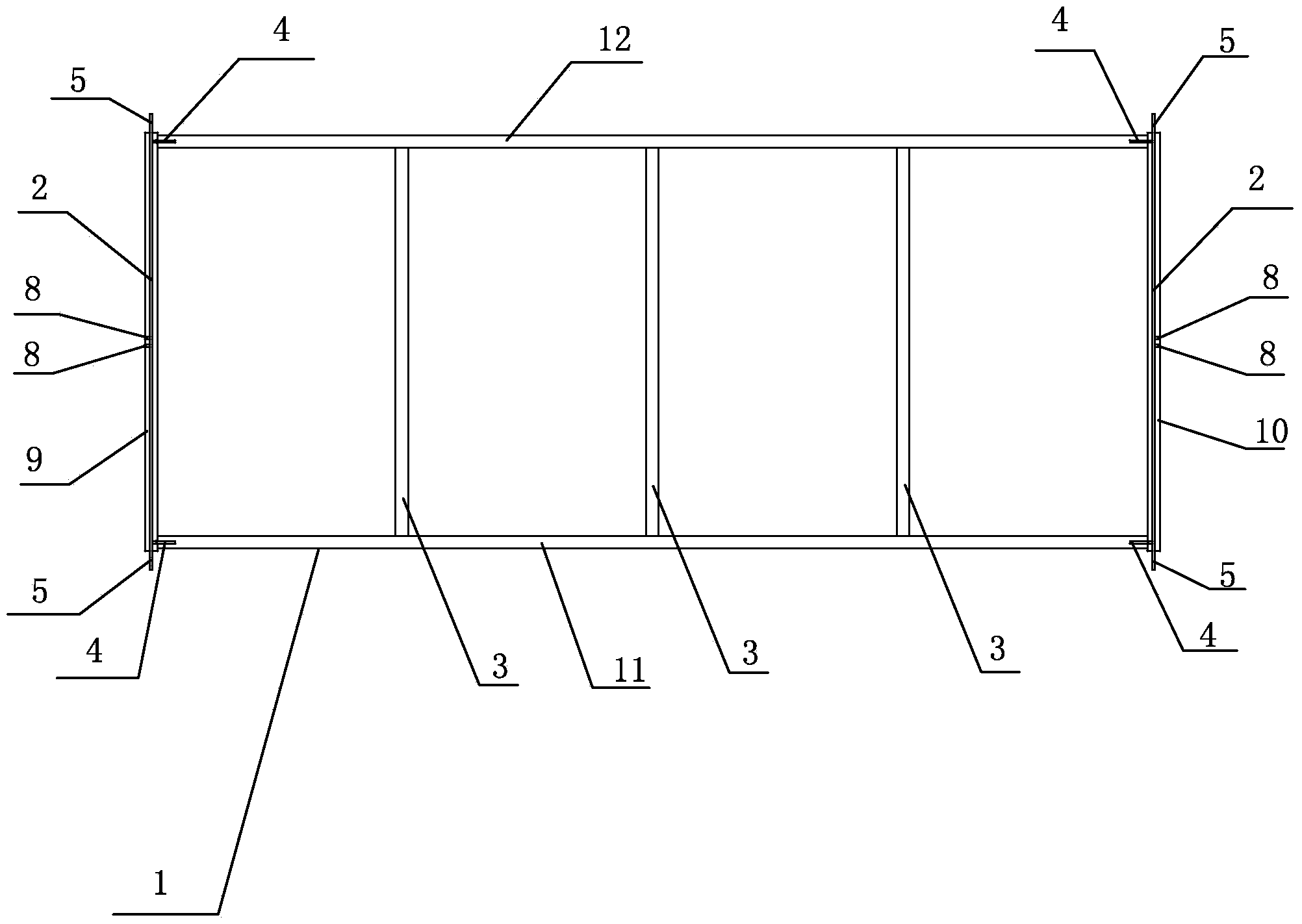
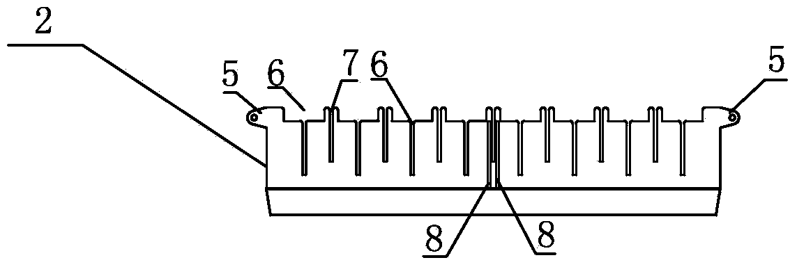
[0019] Such as figure 1 , 2 , 3, a T-row transfer frame tooling, including the first side bar 9, the first cross bar 11, the second side bar 10, the second cross bar 12 connected end to end to form a square T row transfer frame 1; the first side bar 9 and the second side bar 10 of the T row transfer frame 1 are symmetrically installed with a T row support frame 2; the T row support frame 2 is connected to the T row transfer frame 1 through the rib plate 4 respectively The first crossbar 11 and the second crossbar 12 are fixedly connected; the two ends of the T row support frame 2 are symmetrically installed with lifting lugs 5, and the described lifting lugs 5 are integrally formed with the T row support frame 2; A support rod 3 is installed between the first crossbar 11 and the second crossbar 12 of the T-row transfer frame 1 , and the support rod 3 is parallel to the T-row support frame 2 . Such as image 3 As shown, eight slots 6 are provided on the T row support frame 2...
PUM
| Property | Measurement | Unit |
|---|---|---|
| Radius | aaaaa | aaaaa |
Abstract
Description
Claims
Application Information
 - R&D
- Intellectual Property
- Life Sciences
- Materials
- Tech Scout
- Unparalleled Data Quality
- Higher Quality Content
- 60% Fewer Hallucinations
Browse by: Latest US Patents, China's latest patents, Technical Efficacy Thesaurus, Application Domain, Technology Topic, Popular Technical Reports.
© 2025 PatSnap. All rights reserved.Legal|Privacy policy|Modern Slavery Act Transparency Statement|Sitemap|About US| Contact US: help@patsnap.com


