Vacuum generating device of wafer chuck

A technology of vacuum generating device and vacuum generator, which is applied in the manufacture of electrical components, semiconductor/solid state devices, circuits, etc., can solve the problems of waste of compressed air and increase of production cost, so as to improve economic benefits, save production costs, and save compression air effect

Inactive Publication Date: 2014-01-22
SHANGHAI HUAHONG GRACE SEMICON MFG CORP
View PDF4 Cites 2 Cited by
  • Summary
  • Abstract
  • Description
  • Claims
  • Application Information

AI Technical Summary

Problems solved by technology

[0002] In the prior art, the wafer chuck grabs the wafer through vacuum suction, and the vacuum is formed by jetting compressed air. However, generally speaking, the jetted compressed air is always in a conveying state, but the wafer chuck does not It

Method used


Image

  • Vacuum generating device of wafer chuck

Examples


Embodiment Construction

[0010] The present invention will be further elaborated below by describing a preferred specific embodiment in detail in conjunction with the accompanying drawings.

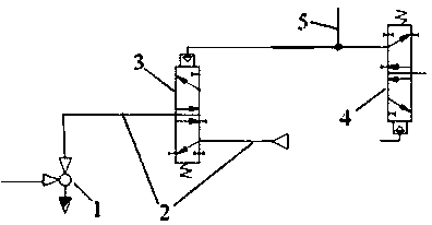
[0011] Such as figure 1 As shown, a vacuum generating device for a wafer chuck includes: a vacuum generator 1 connected through pipelines, a compressed air pipeline 2 and a gas valve 3 . Wherein, the vacuum generator 1 provides vacuum to the wafer chuck; the gas valve 3 is arranged on the compressed air pipeline 2, and the control end of the gas valve 3 is connected to the gas supply pipeline 5 of the working valve 4 of the external wafer chuck through the pipeline.

[0012] When working, the gas supply pipeline 5 provides compressed air to the working valve 4, so that the wafer chuck starts to work, and at the same time, part of the compressed air from the gas supply pipeline 5 enters the control end of the gas valve 3, thereby leading the gas valve 3, with Input compressed air to the vacuum generator 1, and th...


PUM


Abstract

The invention discloses a vacuum generating device of a wafer chuck. The device comprises a vacuum generator and a compressed air pipeline which are connected by a pipeline, wherein the vacuum generator provides vacuum for the wafer chuck. The device further comprises an air valve which is arranged between the vacuum generator and the compressed air pipeline. A control end of the air valve is connected with a gas supply pipeline of a working valve of an external wafer chuck through a pipeline. When the gas supply pipeline supplies compressed air to the working valve, a part of the compressed air is separated to enter the control end of the air valve so that the air valve is switched on and the compressed air can be input to the vacuum generator. The wafer chuck and the vacuum generator are ensured to be synchronous; and when the vacuum generator does not need to work, a large amount of compressed air is saved, the production cost is saved, and the economic efficiency is improved.

Description

technical field [0001] The invention relates to a vacuum generator, in particular to a vacuum generator for a wafer chuck. Background technique [0002] In the prior art, the wafer chuck grabs the wafer through vacuum suction, and the vacuum is formed by jetting compressed air. However, generally speaking, the jetted compressed air is always in a conveying state, but the wafer chuck does not It will always be in working condition, that is, it does not always need to generate vacuum suction, but only needs vacuum suction when grabbing the wafer. Therefore, the long-open compressed air is wasted most of the time, which increases the production cost. Contents of the invention [0003] The purpose of the present invention is to provide a vacuum generating device for a wafer chuck, which ensures the synchronization of the wafer chuck and the vacuum generator; when the vacuum generator does not need to work, it saves a lot of compressed air, saves production costs, and improves ...

Claims


Application Information

Patent Timeline
IPC IPC(8): H01L21/683
CPCH01L21/6838
Inventor 顾军刘波尹绂聿
Owner SHANGHAI HUAHONG GRACE SEMICON MFG CORP
Why Eureka
Try Eureka