A Self-cleaning Structure of Rotor Spinning Machine

A rotor spinning machine and self-cleaning technology, applied in spinning machines, open-end spinning machines, continuous winding spinning machines, etc., can solve the problem of increased labor intensity of operators and dust accumulation in rotor condensing tanks. , low production efficiency and other problems, to reduce the labor intensity of workers, reduce the number of cleaning, and achieve the effect of good uniformity

Inactive Publication Date: 2016-02-24
上海捷春进出口贸易有限公司
View PDF4 Cites 0 Cited by
  • Summary
  • Abstract
  • Description
  • Claims
  • Application Information

AI Technical Summary

Problems solved by technology

However, the secondary raw materials and regenerated fibers with a lot of short staples and high impurities will cause serious dust accumulation in the rotor condensation groove, deterioration of yarn evenness, decrease in strength, increase in end breakage, and the labor intensity of operators will increase significantly. , low production efficiency and other technical problems

Method used


Image

  • A Self-cleaning Structure of Rotor Spinning Machine
  • A Self-cleaning Structure of Rotor Spinning Machine
  • A Self-cleaning Structure of Rotor Spinning Machine

Examples


Embodiment Construction

[0022] Below in conjunction with accompanying drawing, the present invention is described in further detail:

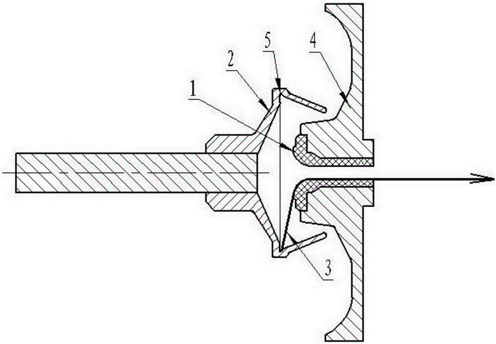
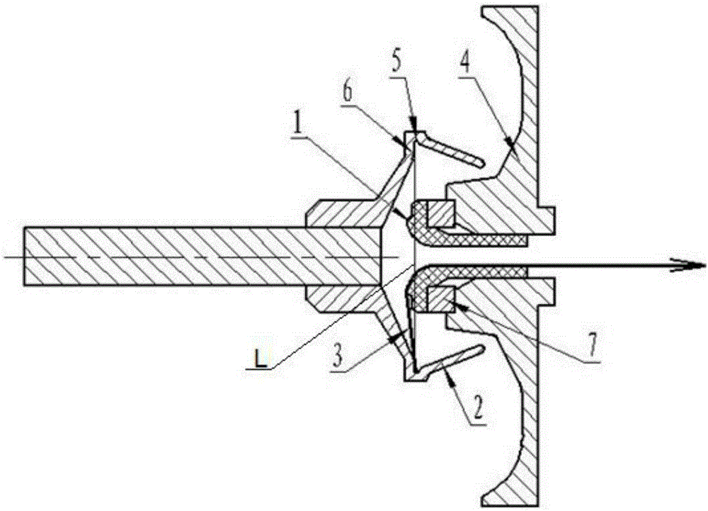
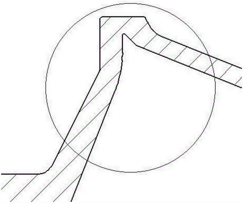
[0023] combine figure 2 As shown, a self-cleaning structure of a rotor spinning machine includes a T-shaped rotor 2 and an upper channel 4 for fiber delivery, and the T-shaped rotor has a condensation groove 5, such as image 3 As shown, the cross section of the condensation groove 5 is an acute angle, and a false twist disk 1 is installed on the upper channel of the fiber delivery, and the false twist disk stretches into the cup mouth of the rotor cup, and the top of the false twist disk (i.e. false twist disk 1) The leftmost side of the twist disc) is close to the bottom of the rotor and passes through the plane L where the bottom surface of the condensation groove 5 is located. The distance between the top of the false twist disk passing through the plane where the bottom surface of the condensation tank is located is 0.5 mm to 1 mm. Preferably, the distance bet...


PUM


Abstract

The invention relates to a self-cleaning structure of a revolving-cup spinning machine. The self-cleaning structure of the revolving-cup spinning machine comprises a T-type revolving cup (2) and a fiber conveying upper channel (4). The T-type revolving cup is provided with a coagulation groove (5). A false twisting disc (1) is installed on the fiber conveying upper channel. The false twisting disc is located inside a cup mouth of the revolving cup. The top end of the false twisting disc is close to the bottom of the revolving cup and penetrates through a plane (L) where the bottom face of the coagulation groove (5) is located. The distance of the portion, penetrating through the bottom plane (L) of the coagulation groove (5), of the top of the false twisting disc is 0.7mm. A cushion block (7) is installed between the false twisting disc and the fiber conveying upper channel. A circular arc transition face (6) is arranged between the bottom plane (L) of the coagulation groove and a slope of the bottom of the revolving cup. In the revolving process of the revolving cup, impurities and dust close to the bottom plane of the coagulation groove can be stirred by tail yarn and sucked by negative pressure formed in the revolving cup from a gap between the cup mouth and the fiber conveying upper channel, and therefore the aim that accumulated dust inside the coagulation groove in the revolving cup is automatically cleaned away is achieved.

Description

technical field [0001] The invention relates to a rotor spinning machine, in particular to a self-cleaning structure of the rotor spinning machine, including a rotor and a fiber feeding upper channel. Background technique [0002] Rotor spinning is a new spinning method that completes fiber transportation, cohesion, merging, and twisting into yarn through a high-speed rotating cup and negative pressure inside the cup. It is the most mature and widely used spinning technology among various new spinning methods. The widest range of spinning technologies. According to the method of generating negative pressure in the rotor, it can be divided into two categories: self-exhausting type and suction type. There is a certain gap between the cup opening of the suction rotor spinning machine and the upper channel of the fiber delivery. The single fiber enters the rotor cup through the fiber delivery channel with the supplementary airflow. Under the centrifugal force of the high-speed...

Claims


Application Information

Patent Timeline
Patent Type & Authority Patents(China)
IPC IPC(8): D01H4/24
Inventor 王旭纯李显彪
Owner 上海捷春进出口贸易有限公司
Why Eureka
Try Eureka