
Novel condensation pipe

A condensing tube, a new type of technology, applied in the field of chemical instruments, can solve the problems of easy damage, high cost, and complicated shape of the condensing tube, and achieve the effect of simple disassembly and avoiding high cost

Inactive Publication Date: 2014-02-12
文圣
View PDF2 Cites 0 Cited by
  • Summary
  • Abstract
  • Description
  • Claims
  • Application Information

AI Technical Summary

Problems solved by technology

[0003] The present invention mainly aims at the problems of complex shape, easy damage and high cost of existing condenser pipes, and provides a new condenser pipe with simple structure, not easy to be damaged, low cost and reusable

Method used


Image

  • Novel condensation pipe

Examples


Embodiment 1

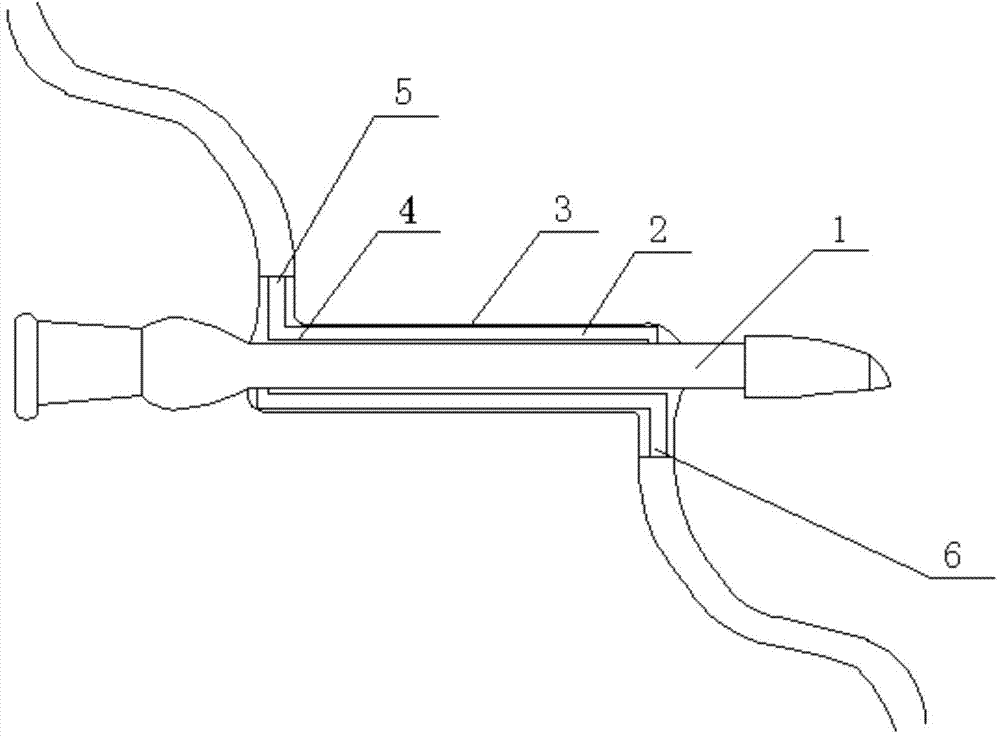
[0010] Such as figure 1 As shown, a new type of condensing tube includes an inner tube 1, wherein a condensing device 2 is provided outside the inner tube 1, and the condensing device 2 is composed of a plastic shell 3 and an annular plastic tube 4 arranged in the plastic shell 3 , The plastic shell 3 is movably connected with the inner tube 1, and the two ends of the annular plastic tube 4 are provided with a water inlet 5 and a water outlet 6 respectively.

[0011] The plastic shell 3 has an arc shape and is clamped on the inner tube 1.


PUM


Abstract

The invention belongs to the technical field of chemical instruments, in particular relates to a novel condensation pipe, mainly solving the problems of complex molding, easy damage and high cost of an existing condensation pipe. The invention adopts the technical scheme that the novel condensation pipe comprises an inner pipe, wherein a condensation device is arranged at the outer part of the inner pipe and comprises a plastic outer shell and an annular plastic pipe arranged in the plastic outer shell; the plastic outer shell is movably connected with the inner pipe; two ends of the annular plastic pipe are respectively provided with a water inlet and a water outlet; the plastic outer shell is arc-shaped and is clamped on the inner pipe. The novel condensation pipe has the advantages of simple structure, difficult damage, low cost and repeatable use.

Description

Technical field [0001] The invention belongs to the technical field of chemical instruments, and specifically relates to a novel condenser tube. Background technique [0002] The condenser tube cooling device is one of the more common instruments in chemical experiments. In the process of heating together or purifying chemical reagents and chemical reaction products, the condenser tube is an indispensable instrument. In the daily laboratory, the condenser tube is made of glass, using three tubes inside, middle and outside. In the specific experimental operation process, a certain part of the instrument is often broken due to careless operation, causing the entire instrument to be unusable. Summary of the invention [0003] The invention mainly aims at the problems of complicated shape, easy damage, high cost and the like of the existing condenser tube, and provides a novel condenser tube with simple structure, not easy to be damaged, low cost, and reusable. [0004] The technical ...

Claims


Application Information

Patent Timeline
Patent Type & Authority Applications(China)
IPC IPC(8): B01L7/00B01L3/00
Inventor 文圣
Owner 文圣
Learn More