
JSG355 speed reducer special for loom
A technology of reducer and loom, which is applied in the direction of looms, textiles, textiles and papermaking, etc., can solve the problems of poor weaving density control accuracy, inability to adjust, and low quality of weaving products, so as to achieve uniform weaving density and improve The effect of weaving quality
- Summary
- Abstract
- Description
- Claims
- Application Information
AI Technical Summary
Problems solved by technology
Method used
Image

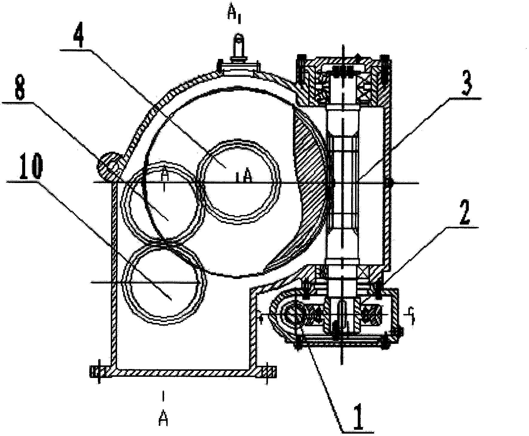
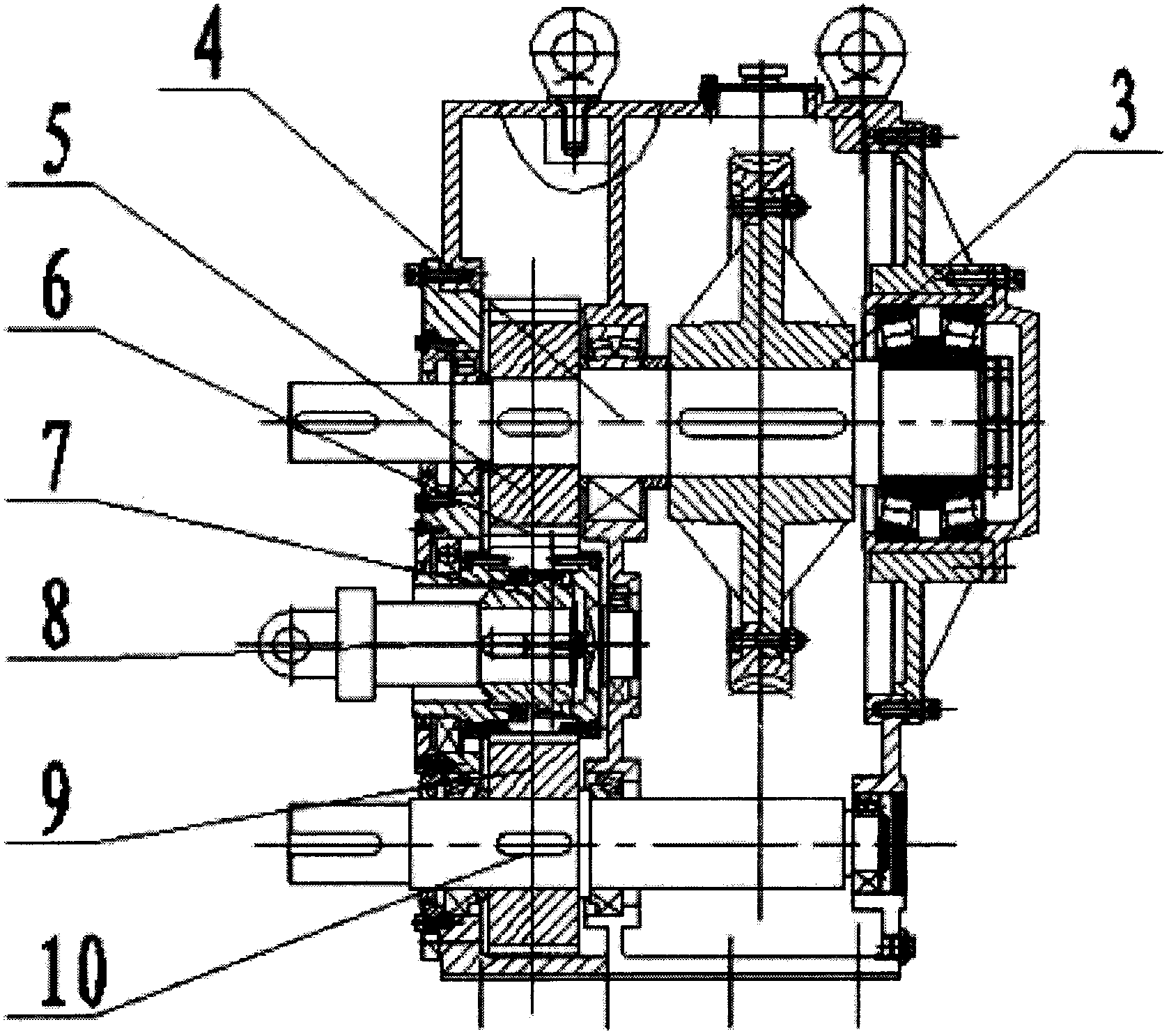
Examples
Embodiment Construction
[0010] The specific implementation manner of the present invention will be further described below in conjunction with the accompanying drawings.
[0011] figure 1 , 2 As shown, a special JSG355 reducer for looms includes an input shaft 1, a small worm gear reducer 2, a large worm gear reducer 3, an upper output shaft 5, an upper gear 6, a middle gear 7, a drum gear 8, and a middle output shaft 9, the lower gear 10 and the lower output shaft 11. The input shaft 1 is connected to the small worm gear reducer 2, the small worm gear reducer 2 is connected to the large worm gear reducer 3, the upper output shaft 4 is connected to the large worm gear reducer 3, the upper output shaft 4 is provided with an upper gear 5, and the upper gear 5 is connected to the middle The gear 6 meshes, the middle gear 6 is internally meshed with a drum gear 7, the drum gear 7 is connected to the middle output shaft 8, the middle gear 6 meshes with the lower gear 9, and the lower gear 9 is connected...
PUM
 Abstract
Description
Claims
Application Information