
Overheating protection button switch

A technology of overheating protection and buttons, which is applied to thermal switch parts and other directions, can solve the problems of easy burnout of button switches, affecting the swing accuracy of conductive seesaw, and poor reliability of buttons, etc.

Inactive Publication Date: 2014-02-12
CHONGQING FENGGUO QIYANG TECH DEV
View PDF0 Cites 5 Cited by
  • Summary
  • Abstract
  • Description
  • Claims
  • Application Information

AI Technical Summary

Problems solved by technology

[0004] The disadvantages of the above method are: ①The slide bar is easy to wear, which affects the swing accuracy of the conductive rocker, resulting in a decrease in the contact sensitivity of the contacts at both ends of the conductive rocker, and the poor reliability of the button operation; ②There is no overload protection device. When the current is high, the button switch is easy to burn out

Method used


Image

  • Overheating protection button switch

Examples


Embodiment Construction

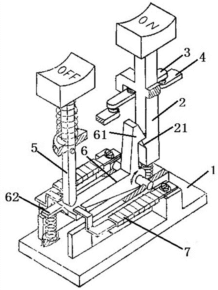
[0011] Such as figure 1 Shown: Overheat protection button switch, including base body 1, on button and off button. The on button consists of a button cap, a connecting rod 2, a movable contact 3 and a fixed contact 4 from top to bottom. The movable contact 3 is installed on the connecting rod 2, and when the connecting rod 2 moves downward, Contact with the fixed contact 4 in order to complete the circuit. The front end of the connecting rod 2 is a chuck 21 with the tip facing upward. The disconnect button comprises a disconnect button cap, a disconnect lever 5 and a return spring. After the disconnect button is pressed, the disconnect button cap and the disconnect lever 5 can return to their original positions under the action of the return spring.

[0012] A claw lever 6 is installed on the seat body 1 along the straight line where the disconnecting lever 5 and the connecting lever 2 are located. The claw lever 6 is hinged on the seat body through the claw lever shaft. The...


PUM


Abstract

The invention belongs to the field of electric switch parts and relates to an overheating protection button switch which comprises a base body, a connecting button and a disconnecting button. The connecting button comprises a button cap, a connecting rod, a movable contact and a fixed contact. The disconnecting button comprises a disconnecting rod and a reset spring. A jaw rod and double metal pieces are arranged on the base body. The jaw rod is fixed on the base body through a jaw rod rotating shaft. A hook jaw and a pressing plate are arranged at the two ends of the jaw rod respectively. The pressing plate is connected with a pressing spring. Deforming ends of the double metal pieces are fixed on the pressing plate. The front end of the connecting rod is provided with a clamping head which can be clamped with the hook jaw. The disconnecting rod abuts against the jaw rod pressing plate. The overheating protection button switch is safe, reliable and high in sensitivity and has a circuit overload protection function.

Description

technical field [0001] The invention belongs to the field of electric switch components. Background technique [0002] Among the various types of electrical switches, the most common are push button switches and rocker switches. Rocker switches generally include a rocker member switchable between at least two selectable stable operating positions corresponding to different selectable modes of operation. Pushbutton switches generally include linearly actuated buttons that are operated by a sequence of simple linear movements. [0003] Most of the existing push button switches adopt the sliding working mode, which is mainly composed of a conductive seesaw, a button, a compression spring, left and right contacts, and a switch base. One end of the compression spring is fixed on the back of the button, and the other end is provided with a slide bar. When the button swings left and right, the torsion force tends to make the slide bar slide on the seesaw, thereby driving and cont...

Claims


Application Information

Patent Timeline
IPC IPC(8): H01H37/52
Inventor 姜静慧
Owner CHONGQING FENGGUO QIYANG TECH DEV
Learn More