
Counterweight device of rotary drilling rig and rotary drilling rig with same

A technology of rotary drilling rig and counterweight device, which is applied in the direction of support device, counterweight, drilling equipment, etc., which can solve the problems of drilling platform losing level, drilling hole not vertical, crawler warping, etc., to protect the drill pipe and improve the drilling efficiency. The effect of improving efficiency and ensuring verticality

Active Publication Date: 2016-07-20
赵鑫宇
View PDF8 Cites 3 Cited by
  • Summary
  • Abstract
  • Description
  • Claims
  • Application Information

AI Technical Summary

Problems solved by technology

[0002] In the field of construction machinery, such as excavators, cranes, rotary drilling rigs, etc., the counterweight device is an indispensable part, which can effectively play the role of front and rear weight balance, but currently the counterweight device is only installed at the rear of the body. The large iron block can only meet the balance weight and has no other functions. However, for construction machinery such as rotary drilling rigs, the drill pipe must be pressed downward during the construction process. If it encounters a hard rock site, it will cause the mast to tilt backward. , Drill pipe tilting, crawler tilting, counterweight sinking, drilling platform loss of level, etc., will also cause the drilling hole to be non-vertical, which will easily cause damage to the drill pipe, and the pressurization force of the equipment cannot be effectively exerted

Method used


Image

  • Counterweight device of rotary drilling rig and rotary drilling rig with same
  • Counterweight device of rotary drilling rig and rotary drilling rig with same

Examples


Embodiment Construction

[0032] The principles and features of the present invention are described below in conjunction with the accompanying drawings, and the examples given are only used to explain the present invention, and are not intended to limit the scope of the present invention.

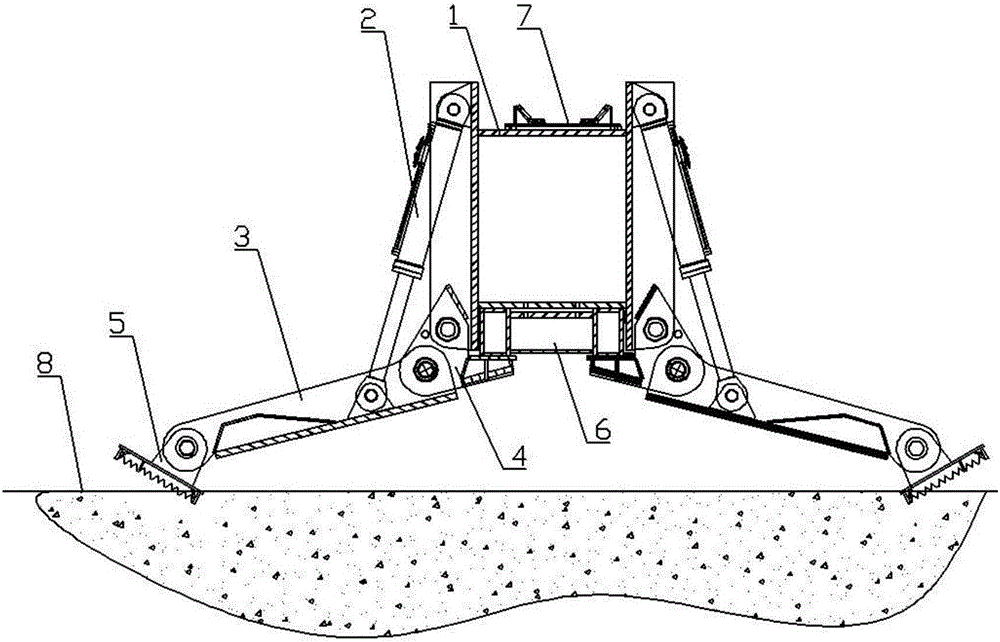
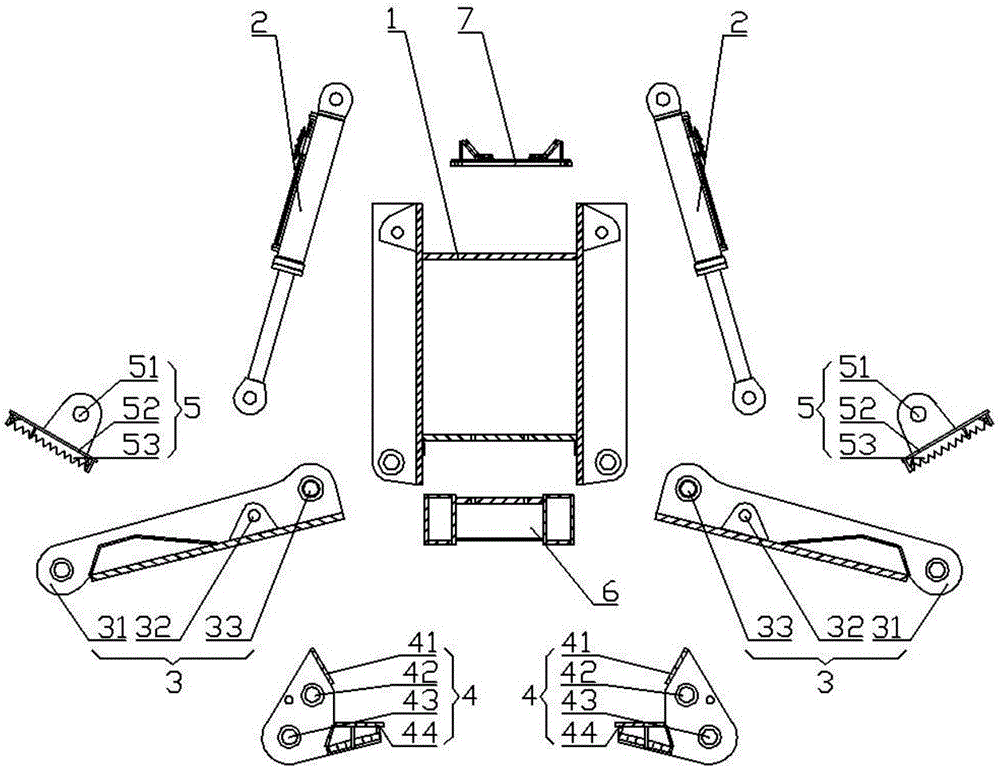
[0033] Such as figure 1 As shown, it is a schematic diagram of a specific embodiment of a rotary drilling rig and its counterweight device provided by the present invention, figure 2 An exploded view of each component.

[0034] A counterweight device of a rotary drilling rig provided by the present invention, the rotary drilling rig includes a machine body and an upper beam 6 installed on the machine body, the counterweight device includes a counterweight box frame 1 for placing counterweight blocks and Outreach outrigger mechanism assembly connected to the outside of the counterweight box frame 1, the counterweight box frame 1 is fixedly installed on the upper part of the boarding beam 6 of the body;

[0035] Th...


PUM


Abstract

The invention discloses a counterweight device of a rotary drilling rig which comprises a rig body and an upper crossbeam mounted on the rig body.The counterweight device comprises a counterweight box frame for placement of a counterweight and an outward-unfolding supporting leg mechanism component connected with the outer side of the counterweight box frame, the counterweight box frame is fixedly mounted on the upper portion of the upper crossbeam of the rig body, the outward-unfolding supporting leg mechanism component comprises an extensible cylinder and a supporting leg, one end of the supporting leg is a supporting end while the other end of the same is hinging end, a middle hinging position is arranged between the supporting end and the hinging end, one end of the extensible cylinder is hinged to the upper portion of the counterweight box frame while the other end of the same is hinged to the middle hinging position of the supporting leg, and the hinging end is hinged to the lower portion of the counterweight box frame.Backward inclination caused by overhigh pressure applied on the ground by the front end can be prevented, so that adaptability and using effect of equipment are improved greatly.The invention further discloses the rotary drilling rig with the counterweight device.

Description

technical field [0001] The invention relates to the field of engineering machinery, in particular to a rotary drilling rig and a counterweight device thereof. Background technique [0002] In the field of construction machinery, such as excavators, cranes, rotary drilling rigs, etc., the counterweight device is an indispensable part, which can effectively play the role of front and rear weight balance, but currently the counterweight device is only installed at the rear of the body. The large iron block can only meet the balance weight and has no other functions. However, for construction machinery such as rotary drilling rigs, the drill pipe must be pressed downward during the construction process. If it encounters a hard rock site, it will cause the mast to tilt backward. Problems such as tilting of the drill pipe, tilting of the crawler, sinking of the counterweight, and loss of level of the drilling platform will also cause the drilling hole to be non-vertical, which wil...

Claims


Application Information

Patent Timeline
IPC IPC(8): E21B15/00F16F15/28
CPCE21B15/00F16F15/28
Inventor 赵鑫宇胡连奇
Owner 赵鑫宇
Learn More