Die casting equipment and method

A mold die-casting and equipment technology, applied in the field of die-casting equipment and die-casting, can solve the problems of reducing the production and processing efficiency of products, increasing the production and processing procedures of products, etc., and achieve the effect of increasing the use effect, increasing the performance, and improving the efficiency.

Active Publication Date: 2021-02-12
临沂市铸信机械有限公司
View PDF21 Cites 3 Cited by
  • Summary
  • Abstract
  • Description
  • Claims
  • Application Information

AI Technical Summary

Problems solved by technology

[0002] When using mold die-casting equipment to produce and process products, the raw materials are injected into the cavity of the fixed mold, and the movable mold is moved down and inserted into the cavity of the fixed mold to form a certain shape of the raw material. After the raw material is cooled and formed, it forms a production process. However, when the fixed mold moves down and is inserted into the cavity of the fixed mold, it will squeeze the raw materials in the cavity of the fixed mold, causing some raw materials to overflow from the cavity of the fixed mold after being squeezed and move to the movable mold cavity. The area between the mold and the fixed mold will cause redundant parts on the top of the product after cooling and forming, which needs to be processed again by the staff, which increases the production and processing procedures of the product and reduces the efficiency of product production and processing. Therefore, we propose Mold die-casting equipment and die-casting method

Method used


Image

  • Die casting equipment and method
  • Die casting equipment and method
  • Die casting equipment and method

Examples


Embodiment Construction

[0022] The following will clearly and completely describe the technical solutions in the embodiments of the present invention with reference to the accompanying drawings in the embodiments of the present invention. Obviously, the described embodiments are only some, not all, embodiments of the present invention. Based on the embodiments of the present invention, all other embodiments obtained by persons of ordinary skill in the art without making creative efforts belong to the protection scope of the present invention.

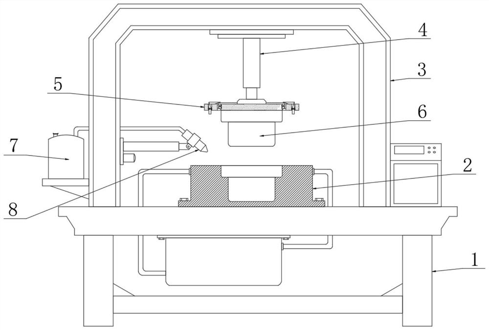
[0023] The present invention provides a technical solution: die casting equipment, please refer to figure 1 , including workbench 1;

[0024] see figure 1 , the top outer wall of the workbench 1 is fixedly installed with a fixed mold 2, the top outer wall of the workbench 1 is fixedly connected with the frame 3, the top inner wall of the frame 3 is fixedly connected with the hydraulic cylinder 4, and the hydraulic rod at the bottom of the hydraulic cylinder 4...


PUM


Abstract

The invention discloses die casting equipment, and belongs to the technical field of die casting equipment. The die casting equipment comprises a workbench, a fixed die is fixedly installed on the outer wall of the top of the workbench, the outer wall of the top of the workbench is fixedly connected with a rack, the inner wall of the top of the rack is fixedly connected with a hydraulic cylinder,a hydraulic rod at the bottom of the hydraulic cylinder is fixedly connected with a cleaning device, a movable die is arranged on the outer wall of the bottom of the cleaning device, a storage barrelis arranged on the outer wall of the left side of the rack, the outer wall of the top of the storage barrel communicates with a material injection head through a guide pipe, and the right end of an electric telescopic rod is connected with the material injection head through a clamp. When the movable die in the device is inserted into a cavity of the fixed die to machine a product, an installationplate can be in contact with the top wall of the fixed die, a movable rod is pushed upwards, a guide block moves towards the inner side, a movable sleeve drives a cutter to move downwards to be in contact with the top wall of the fixed die, overflowing raw materials are cut off, and the circumstance that the top of the product has redundant parts after the raw materials are cooled and formed is avoided.

Description

technical field [0001] The invention relates to the technical field of mold die-casting equipment, in particular to mold die-casting equipment and a die-casting method. Background technique [0002] When using mold die-casting equipment to produce and process products, the raw materials are injected into the cavity of the fixed mold, and the movable mold is moved down and inserted into the cavity of the fixed mold to form a certain shape of the raw material. After the raw material is cooled and formed, it forms a production process. However, when the fixed mold moves down and is inserted into the cavity of the fixed mold, it will squeeze the raw materials in the cavity of the fixed mold, causing some raw materials to overflow from the cavity of the fixed mold after being squeezed and move to the movable mold cavity. The area between the mold and the fixed mold will cause redundant parts on the top of the product after cooling and forming, which needs to be processed again by...

Claims


Application Information

Patent Timeline
Patent Type & Authority Applications(China)
IPC IPC(8): B22D18/02B22D31/00
CPCB22D18/02B22D31/00
Inventor 郭凯
Owner 临沂市铸信机械有限公司
Why Eureka
Try Eureka