Fixture for clamping steam inlet and outlet sides of intermediates of blade roots during milling

An intermediate, steam-side technology, applied in the field of clamping fixtures for milling blade root intermediates in and out of the steam side, can solve the problems of wasting manpower, complicated operations, and a large number of fixtures, and achieves low manufacturing cost, simple operation, and easy maintenance. maintenance effect

Active Publication Date: 2014-02-19
HARBIN TURBINE
View PDF5 Cites 17 Cited by
  • Summary
  • Abstract
  • Description
  • Claims
  • Application Information

AI Technical Summary

Problems solved by technology

[0003] In order to solve the problem of large number of fixtures, waste of manpower, management and cumbersome operation when clamping the intermediate body of the blade root

Method used


Image

  • Fixture for clamping steam inlet and outlet sides of intermediates of blade roots during milling
  • Fixture for clamping steam inlet and outlet sides of intermediates of blade roots during milling

Examples


specific Embodiment approach 1

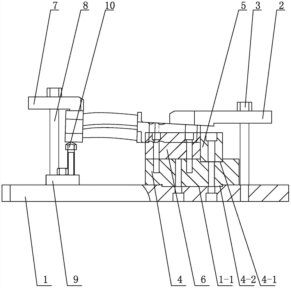
[0007] Specific implementation mode one: combine figure 1 and figure 2 Describe this embodiment, a fixture for clamping the inlet and outlet steam sides of the milling blade root intermediate body described in this embodiment includes a bottom plate 1, a slope pressure plate mechanism, a flat pressure plate 2, a first double-ended stud 3, a guide slider 4, a positioning Slider 5 and baffle plate 6, bottom plate 1 is arranged horizontally, the lower end of first double-ended stud 3 is inserted on the upper surface of bottom plate 1, and the upper end of first double-ended stud 3 is connected with platen 2, and platen 2 The lower surface of the bottom plate is parallel to the upper surface of the bottom plate 1, the guide slider 4 is arranged on the upper surface of the bottom plate 1, and the guide slider 4 is located under the flat plate 2, and the positioning slider 5 and the baffle plate 6 are installed side by side through a plurality of bolts On the upper surface of the ...

specific Embodiment approach 2

[0008] Specific implementation mode two: combination figure 1 and figure 2 This embodiment is described. The slope clamping mechanism of the clamp for the inlet and outlet steam side of the milling blade root intermediate in this embodiment includes the slope clamping plate 7, the second double-ended stud 8, the base 9 and the hexagonal head support 10, The base 9 is installed on the upper surface of the base plate 1, the lower end of the second double-ended stud 8 is inserted on the base 9, the slope pressing plate 7 is installed on the upper end of the second double-ended stud 8, and the lower end of the slope pressing plate 7 The surface is parallel to the upper surface of the bottom plate 1 , the hexagonal head support 10 is installed on the upper surface of the base 9 , and the hexagonal head support 10 is located below the slope pressing plate 7 .

[0009] The technical effect of this embodiment is: such arrangement enables blades of different models and types to be ac...

specific Embodiment approach 3

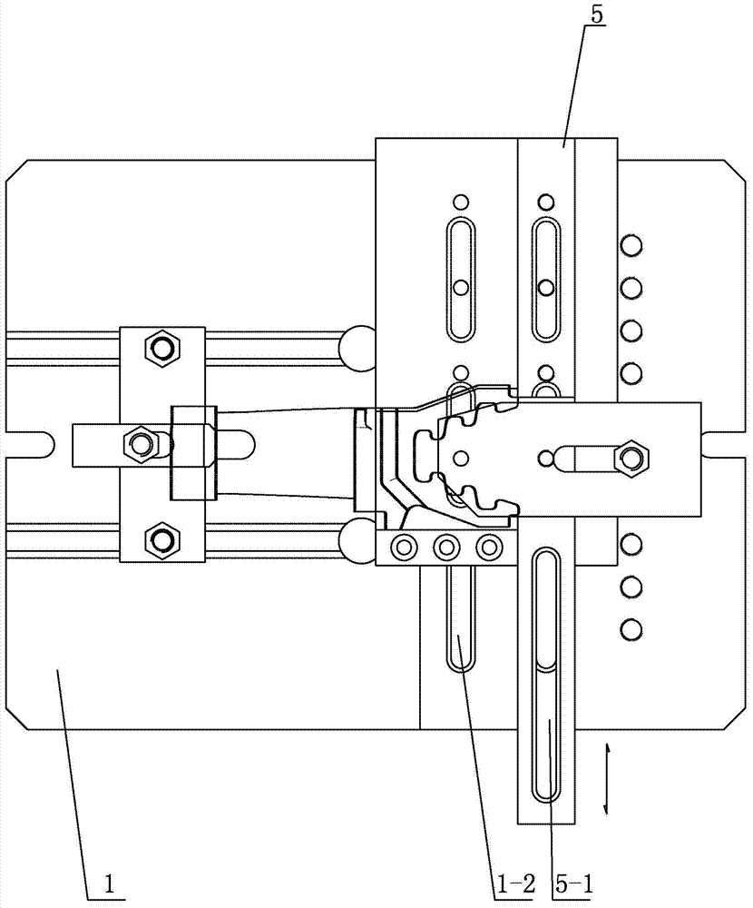
[0010] Specific implementation mode three: combination figure 1 and figure 2 To illustrate this embodiment, the guide slider 4 of the clamp for the inlet and outlet steam side of the milling blade root intermediate described in this embodiment is a cuboid, and the upper surface of the guide slider 4 is provided with a first rectangular chute 4-1, and The first rectangular chute 4-1 is parallel to the centerline of the guide slider 4 along the longitudinal direction along the length square centerline, and the positioning slider 5 is inserted in the first rectangular chute 4-1.

[0011] The technical effect of this embodiment is: such setting enables the positioning slider 5 to be adjusted at any time according to the shape and position of the blade, ensuring the accuracy of installation. Other compositions and connections are the same as those in Embodiment 1 or 2.


PUM


Abstract

The invention discloses a fixture for clamping steam inlet and outlet sides of intermediates of blade roots during milling, and relates to a fixture. The fixture comprises a bottom plate, an oblique pressure plate mechanism, a flat pressure plate, a first double-end stud, a guide slider, a positioning slider and a barrier. The bottom plate is horizontally arranged, the lower end of the first double-end stud is inserted in the upper surface of the bottom plate, the upper end of the first double-end stud is connected with the flat pressure plate, the lower surface of the flat pressure plate is parallel to the upper surface of the bottom plate, the guide slider is arranged on the upper surface of the bottom plate and is positioned below the flat pressure plate, the positioning slider and the barrier are mounted on the upper surface of the guide slider side by side via a plurality of bolts, and the oblique pressure plate mechanism is arranged on the upper surface of the bottom plate. The fixture has the advantages that problems of large quantities of fixtures, waste of labor and troublesome management and operation when intermediates of blade roots of blades of steam turbines are clamped during milling can be solved; the fixture is used for blade machining.

Description

technical field [0001] The invention relates to a fixture, in particular to a fixture for clamping the steam inlet and outlet sides of a milling blade root intermediate body. Background technique [0002] Although the blade roots of steam turbine blades belong to a series and are similar, they have various sizes, and there are the following technical difficulties in clamping. Due to the various sizes of blade roots, it is difficult to guarantee the requirements of a series of blades in one clamping. Fixtures, the number of fixtures is large, wastes manpower, and the operation is very cumbersome at the same time. Contents of the invention [0003] In order to solve the problems of large number of fixtures, waste of manpower, management and cumbersome operation when clamping the intermediate body of the blade root of the milling steam turbine, the present invention further proposes a clamp for clamping the steam inlet and outlet sides of the intermediate body of the milling ...

Claims


Application Information

Patent Timeline
IPC IPC(8): B23Q3/06
CPCB23Q3/063
Inventor 张宇航宋洪明贺严付婷婷朱建军吴雯莉董美会张树纲
Owner HARBIN TURBINE
Why Eureka
Try Eureka