A kind of mems microphone structure and manufacturing method thereof

A manufacturing method and microphone technology, applied in the direction of electrostatic transducer microphone, etc., can solve the problem of back electrode falling off, and achieve the effect of reducing capacitance and improving sensitivity

Active Publication Date: 2018-12-18
SHANGHAI INTEGRATED CIRCUIT RES & DEV CENT
View PDF5 Cites 0 Cited by
  • Summary
  • Abstract
  • Description
  • Claims
  • Application Information

AI Technical Summary

Problems solved by technology

A problem with this method is that when the release process is performed to remove the dielectric layer between the vibrating membrane and the back electrode and between the back electrode and the substrate to form an air gap, the release process time needs to be strictly controlled. Long time will completely remove the dielectric layer under the back electrode and cause the back electrode to fall off

Method used


Image

  • A kind of mems microphone structure and manufacturing method thereof
  • A kind of mems microphone structure and manufacturing method thereof
  • A kind of mems microphone structure and manufacturing method thereof

Examples


Embodiment Construction

[0022] In order to make the content of the present invention clearer and easier to understand, the content of the present invention will be further described below in conjunction with the accompanying drawings. Of course, the present invention is not limited to this specific embodiment, and general replacements known to those skilled in the art are also covered within the protection scope of the present invention.

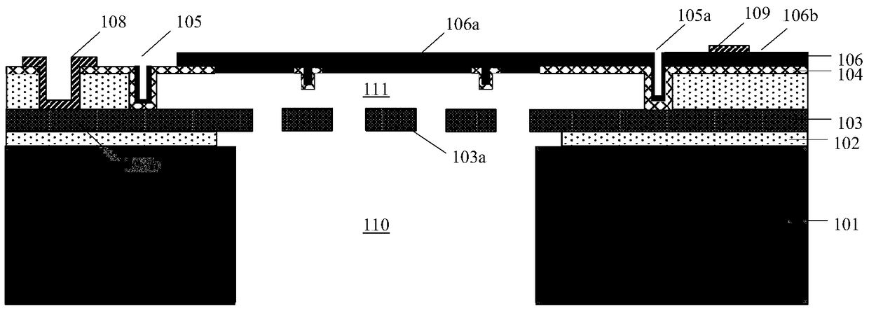
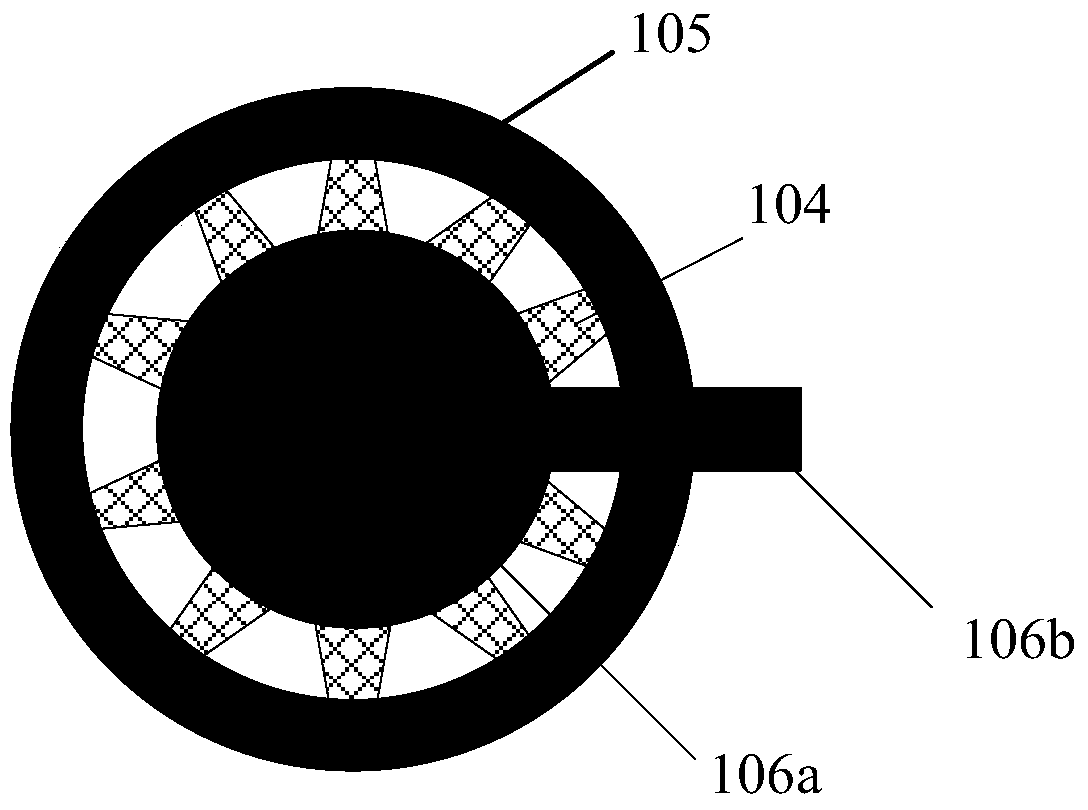
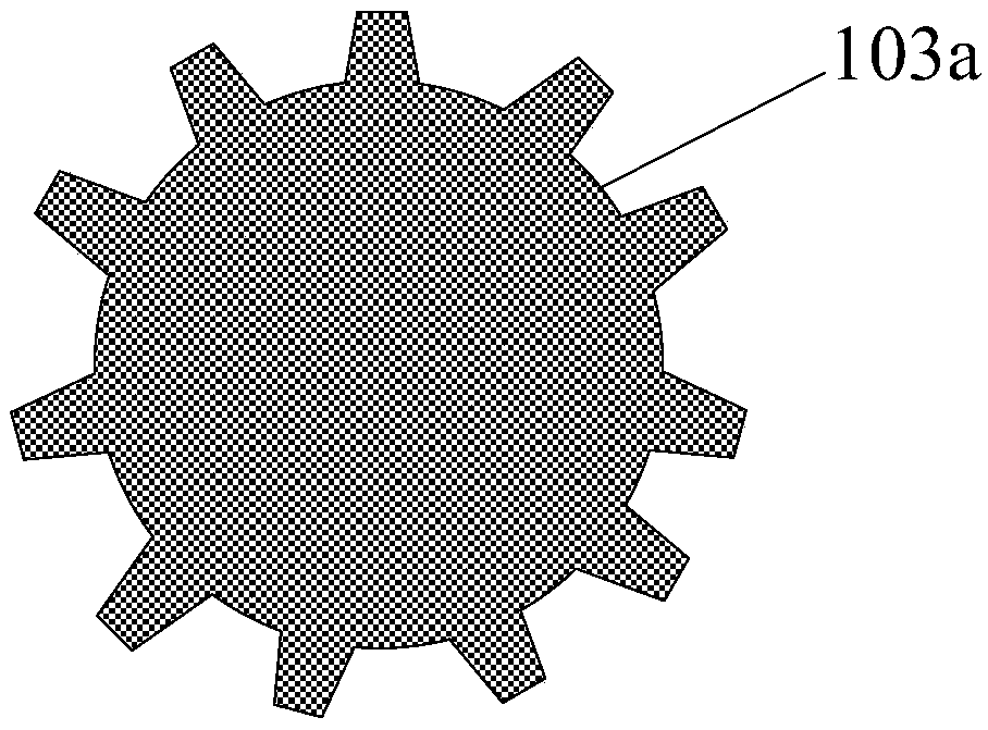
[0023] First, the structure of a MEMS microphone according to an embodiment of the present invention will be described. like figure 1 As shown, the MEMS microphone structure includes a semiconductor substrate 101, a first dielectric layer 102, a lower electrode layer 103 and an upper electrode structure. Wherein, a cavity 110 is formed in the substrate, and its shape may be cylindrical or conical. The first dielectric layer 102 is formed on the upper surface of the semiconductor substrate 101 and has a through hole communicating with the cavity 110 . The lower e...


PUM


Abstract

The invention discloses an MEMS microphone structure which comprises a substrate, a first dielectric layer, a lower electrode layer, an upper electrode structure, an air gap and a release hole. The substrate includes a cavity; the first dielectric layer includes a through hole communicated with the cavity; the lower electrode layer comprises a backplate and a first leading-out portion which are connected with each other, and the backplate is placed over the through hole; the upper electrode structure comprises a diaphragm formed by an upper electrode layer, a second leading-out portion connected with the diaphragm, and an annular groove filled with an insulating layer; the bottom of the annular groove is supported by the lower electrode layer and placed in areas beyond the backplate; the insulating layer extends horizontally inwardly from the upper end of the inner sidewall of the annular groove to position under the diaphragm so that the diaphragm is hung over the backplate via the annular groove; the air gap is formed between the diaphragm and the backplate; and the release hole is formed in the backplate and communicated with the air gap and the through hole. According to the invention, the backplate and diaphragm can be avoided from damage or falling off in the release process.

Description

technical field [0001] The invention relates to the technical field of micro-electro-mechanical systems, in particular to a MEMS microphone structure and a manufacturing method thereof. Background technique [0002] Microphones are divided into dynamic microphones and condenser microphones. The traditional dynamic microphone consists of a coil, a diaphragm and a permanent magnet. It is based on the principle that the movement of the coil in a magnetic field generates an induced current; while the main structure of a capacitive microphone is two capacitive plates, namely the diaphragm (Diaphragm ) and the back electrode (Backplate), its working principle is that the sound pressure causes the deformation of the vibrating membrane, resulting in a change in the capacitance value, which is converted into an electrical signal output. [0003] MEMS microphones are by far one of the most successful MEMS products. MEMS microphone is a microphone manufactured by surface processing o...

Claims


Application Information

Patent Timeline
Patent Type & Authority Patents(China)
IPC IPC(8): H04R19/04
Inventor 康晓旭袁超左青云
Owner SHANGHAI INTEGRATED CIRCUIT RES & DEV CENT
Why Eureka
Try Eureka