Method for rapidly replacing strained sieve net and vibration sieve

A technology of vibrating sieve and stretching net, which is applied in chemical instruments and methods, sieving, solid separation, etc. It can solve the problems of large impact caused by production, achieve the effect of convenient operation, simplify the replacement process, and save the time for changing the screen

Inactive Publication Date: 2014-03-05
卢海勇
View PDF8 Cites 4 Cited by
  • Summary
  • Abstract
  • Description
  • Claims
  • Application Information

AI Technical Summary

Problems solved by technology

The longer it takes to replace the screen, the greater the impact on production
In the industry, there has been no good solution for fast and convenient screen replacement and high-quality effective tensioning of the screen

Method used


Image

  • Method for rapidly replacing strained sieve net and vibration sieve
  • Method for rapidly replacing strained sieve net and vibration sieve
  • Method for rapidly replacing strained sieve net and vibration sieve

Examples


Embodiment 1

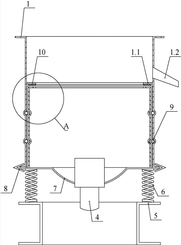
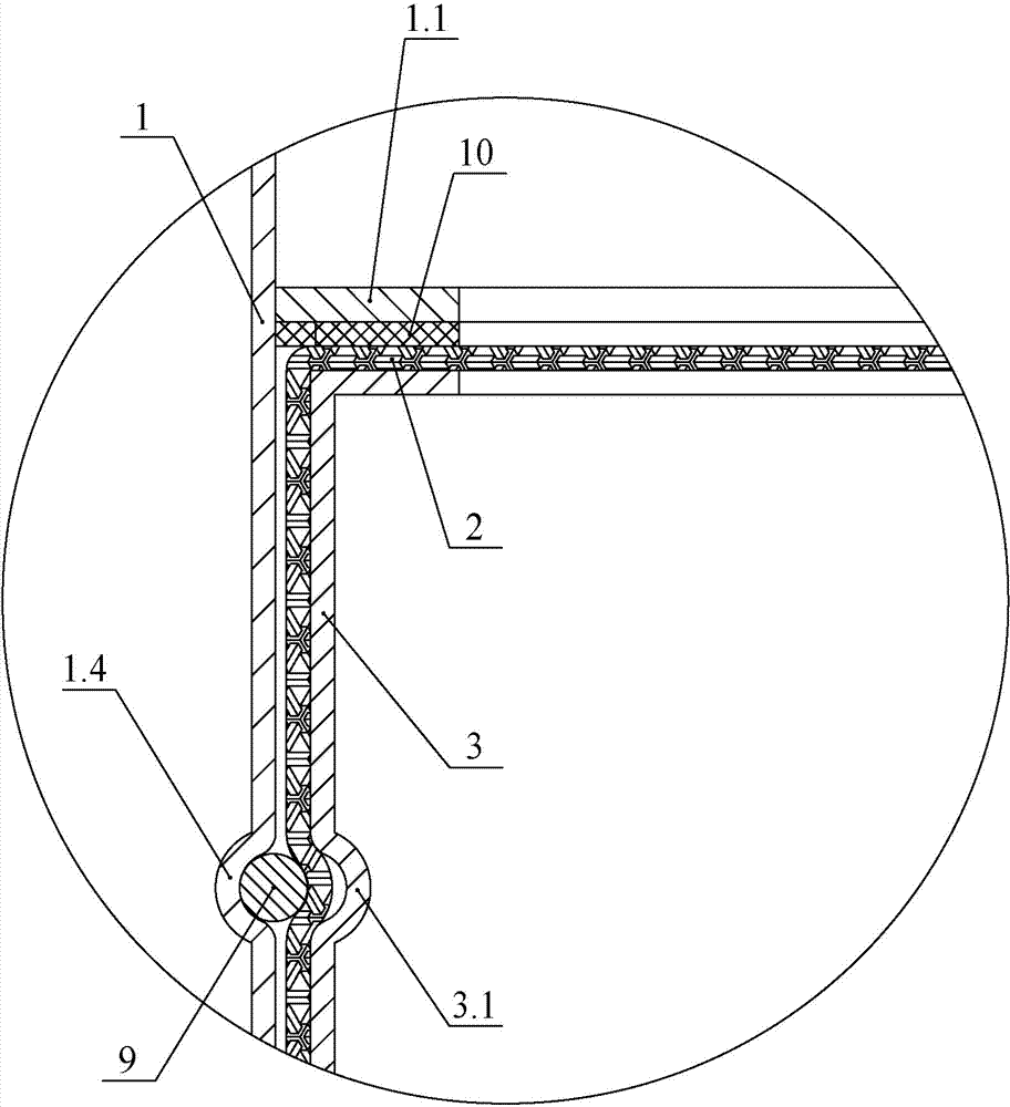
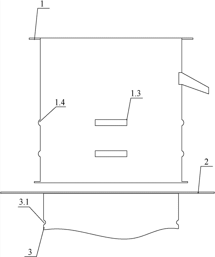
[0041] Such as figure 1 , 4 , Shown in 5, vibrating screen of the present invention is mainly made up of screen frame 1, screen cloth 2, grid frame 3, vibrating motor 4, base 5, vibrating spring 6 and vibrating body 7. The grid frame 3 is located in the cavity surrounded by the screen frame 1, and an annular cavity is formed between the grid frame 3 and the screen frame 1. The screen cloth 2 is tightened on the grid frame 3 by stretching hoops 9 . Start the vibrating motor 4, the vibrating body 4 vibrates, the large particle slag remaining on the upper surface of the screen 2 is discharged from the slag discharge port 1.2, and the fine material leaks from the screen.

[0042] In this embodiment, the inner wall of the screen frame 1 and the outer wall of the grid frame 3 are provided with corresponding annular grooves 1.4, and an annular stretching hoop 9 is placed in the annular groove on the screen frame 1, and the outer wall of the screen frame 1 Offer through hole on the...

Embodiment 2

[0054] Compared with Embodiment 1, in this embodiment, the ends of the stretching hoops 9 are still intersected after passing through the screen frame 1 . The difference from Embodiment 1 is that in this embodiment, the stretching net hoop 9 is tightened by straight pulling. Such as Figure 6 As shown, the locking buckle 13 is fixed at the end of the stretching hoop 9, and the hook 12 is fixed on the outer wall of the screen frame 1. Pull the locking buckle 13 by hand to pull one end of the stretching net hoop 9 forward, hang it on the hook 12 after tightening, and then pull the locking piece of the locking buckle 13 to close the stretching net hoop 9 Tight fix.

[0055] This embodiment does not need tools to tighten, only needs to be pulled by hand, the advantage is that it is faster.

[0056] In the above-mentioned first and second embodiments, the ends of the stretching hoops 9 pass through the screen frame 1 and then intersect to realize the tightening of the screen in ...

Embodiment 3

[0058] Different from Embodiments 1 and 2, in this embodiment, the hoops 9 of the stretched mesh do not need to pass through the screen frame. Such as Figure 7 as shown,

[0059] The stretching hoops on the same layer are two semicircles, and the two stretching hoops are correspondingly arranged to form a ring, and the end of one of the stretching hoops is relatively close to the corresponding end of the other stretching hoop. Fix the coupling piece 16 at the end of the stretching net hoop bar 9, penetrate the fastening bolt 14 in the two relative coupling pieces, and set the nut 15 on the fastening bolt 14.

[0060] Open the operation hole 1.3 at the position of the screen frame 1 corresponding to the end of the stretching hoop 9, extend the wrench from the operating hole and twist the nut 15, and the two stretching hoops 9 are relatively tightened, and the screen can be tightened ,No longer. The so-called opening of the operation hole at the position corresponding to the...


PUM


Abstract

The invention relates to the field of the material sieving technology, in particular to a method for rapidly replacing a strained sieve net and a vibration sieve. The vibration sieve comprises a sieve frame, a net frame, the sieve net and a net straining strake. The net frame is arranged in the sieve frame. The vibration sieve is characterized in that the net straining strake is arranged on the inner wall of the sieve frame, a through hole is formed in the position, corresponding to the net straining strake, of the sieve frame, and an end portion of the net straining strake is penetrated out of the through hole; when the sieve net is replaced, the sieve net is horizontally placed on the net frame, the sieve frame is placed on another sieve net and falls off, and the sieve net is attached to the outer wall of the net frame after the sieve frame bends the sieve net downwards; an end portion of the net straining strake is linked with a straining device, and the net straining strake can be tightened by operating the straining device. As the sieve frame and the net straining strake are of an integral structure, when the sieve net is replaced, the sieve net just needs to be flatly placed at the upper end of the net frame, and then the sieve frame is placed on the sieve net and falls off at a time. The sieve frame vertically falls off to bend the sieve net so that the sieve net can be attached to the outer wall of the net frame. The sieve net does not need to be manually bent and the requirement for the skill proficiency of an operator does not exist.

Description

technical field [0001] The invention belongs to the technical field of material screening, and in particular relates to a vibrating screen. Background technique [0002] Enterprises widely use vibrating screens to sort materials. Commonly used vibrating screens include structural components such as screen frames, grid frames, screen meshes, stretching hoops, springs connected to the screen frames, and vibration motors. The screen is vibrated by starting the vibrating motor, so that the small particles pass through the screen and leak down, and the large particles are blocked on the screen. The screen used in the vibrating screen is generally woven with metal wire, nylon wire, etc. The screen is a vulnerable part and needs to be replaced after a period of use. An important factor affecting the use effect of the vibrating screen is whether the screen can be tightened. The tighter the screen is, the better the vibrating screening effect is and the longer the service life is. ...

Claims


Application Information

Patent Timeline
Patent Type & Authority Applications(China)
IPC IPC(8): B07B1/28B07B1/42B07B1/48
Inventor 赵维珂
Owner 卢海勇
Why Eureka
Try Eureka