Method for rapidly replacing screen and flexibly distributing material and vibrating screen

A vibrating sieve and material distribution technology, which is applied to chemical instruments and methods, sieves, solid separation, etc., can solve the problems of weakening the impact force of falling, damage to the screen, and increasing the burden on the vibration motor, so as to buffer the falling speed and simplify the replacement process , The effect of saving the time of changing the screen

Inactive Publication Date: 2015-06-10
盐城万恒家纺有限公司
View PDF3 Cites 0 Cited by
  • Summary
  • Abstract
  • Description
  • Claims
  • Application Information

AI Technical Summary

Problems solved by technology

[0012] (1) Due to the fast flow rate of the slurry, when the slurry is poured from a certain height to the screen, it will have a greater impact on the screen, which is easy to cause damage to the screen and affect the service life of the screen.
[0013] (2) When the slurry is poured on the screen, the speed is fast, so that the screen has no time to screen the slurry, so more and more slurry will be poured on the screen, and the pressure generated by too much slurry will also cause Damage to the screen and increase the burden on the vibrating motor, reducing the service life of the vibrating screen
[0014] (3) The slurry falls at a faster speed, so it splashes around after falling on the screen, which pollutes the environment of the workplace and also causes a waste of slurry
In the industry, there has been no good solution for quick replacement of the screen, high-quality effective tensioning of the screen, and uniform distribution of materials to reduce the impact of falling.

Method used


Image

  • Method for rapidly replacing screen and flexibly distributing material and vibrating screen
  • Method for rapidly replacing screen and flexibly distributing material and vibrating screen
  • Method for rapidly replacing screen and flexibly distributing material and vibrating screen

Examples


Embodiment 1

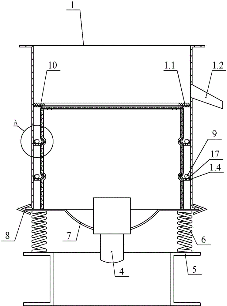
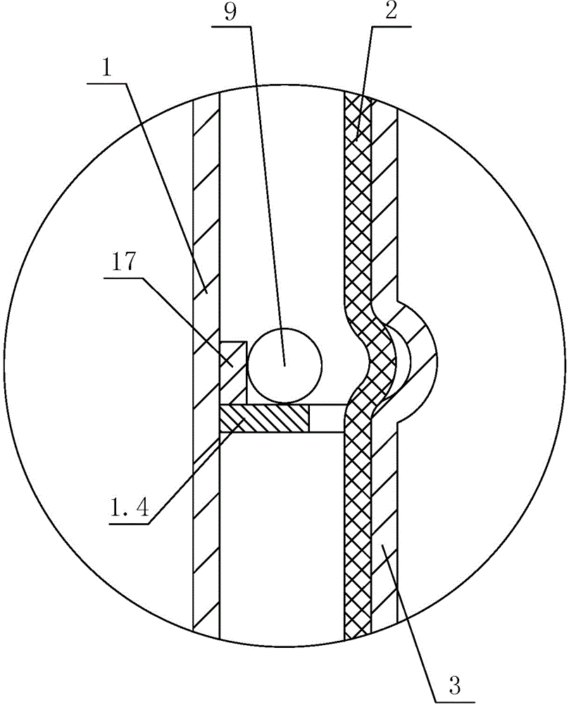
[0046] Such as figure 1 , 3 , 8, and 9, the vibrating screen of the present invention is mainly composed of a screen frame 1, a screen cloth 2, a grid frame 3, a vibrating motor 4, a base 5, a vibrating spring 6 and a vibrating body 7. The grid frame 3 is located in the cavity surrounded by the screen frame 1, and an annular cavity is formed between the grid frame 3 and the screen frame 1. The screen cloth 2 is tightened on the grid frame 3 by stretching hoops 9 . A homogenizer 18 is set above the screen 2, and there is a gap between the homogenizer 18 and the screen 2; a connected hopper 19 and a distribution pan 20 are arranged in the homogenizer 18, and a discharge channel 19.1 is provided at the lower end of the hopper 19. , The bottom of the cloth pan 20 is provided with a cloth opening 20.1. The cloth opening 20.1 is arc-shaped. The edge of the distribution pan 20 is provided with a shroud 20.2, and the middle portion of the shroud 20.2 near the center of the screen ...

Embodiment 2

[0061] Compared with Embodiment 1, in this embodiment, the ends of the stretching hoops 9 are still intersected after passing through the screen frame 1 . The difference from Embodiment 1 is that in this embodiment, the stretching net hoop 9 is tightened by straight pulling. Such as Figure 6 As shown, the locking buckle 13 is fixed at the end of the stretching hoop 9, and the hook 12 is fixed on the outer wall of the screen frame 1. Pull the locking buckle 13 by hand to pull one end of the stretching net hoop 9 forward, hang it on the hook 12 after tightening, and then pull the locking piece of the locking buckle 13 to close the stretching net hoop 9 Tight fix.

[0062] This embodiment does not need tools to tighten, only needs to be pulled by hand, the advantage is that it is faster.

[0063] In Embodiments 1 and 2 above, the ends of the stretching hoops 9 pass through the screen frame 1 and then intersect, so that the screen 2 is tightened in the external space of the sc...

Embodiment 3

[0065] Different from Embodiments 1 and 2, in this embodiment, the stretching hoops 9 do not need to pass through the screen frame 1 . Such as Figure 7 As shown, the stretching hoops 9 of the same layer are two semicircles, and the two stretching hoops 9 are correspondingly arranged to form a ring, and the end of one stretching hoop 9 is connected to the end of the other stretching hoop 9. The corresponding ends are relatively close to each other. Fix the coupling piece 16 at the end of the stretching net hoop bar 9, penetrate the fastening bolt 14 in the two relative coupling pieces 16, and set the nut 15 on the fastening bolt 14.

[0066] An operating hole 1.3 is set at the position of the screen frame 1 corresponding to the end of the stretching hoop 9, and a wrench is inserted into the operating hole 1.3 to turn the nut 15, and the two stretching hoops 9 are relatively tightened, and the screen 2 Straighten it up and say no more. The meaning of opening the operation ho...


PUM


Abstract

A method for rapidly replacing a screen and flexibly distributing material and a vibrating screen belong to the technical field of material screening. The vibrating screen comprises a screen frame, a screen support, the screen and screen-tightening hoop strips, the screen support is located in the screen frame, the vibrating screen is characterized in that the screen-tightening hoop strips are placed on the internal wall of the screen frame, the screen frame is provided with through holes at positions corresponding to the screen-tightening hoop strips, and the ends of the screen-tightening hoop strips pass through the through holes. During screen replacement, a screen is first placed flat on the screen support, the screen frame is then placed on the screen and drops, and after being downwardly bent by the screen frame, the screen clings to the external wall of the screen support; the ends of the screen-tightening hoop strips are connected with tighteners and tightened by operating the tighteners. Because the screen frame is integrated with the screen-tightening hoop strips, during screen replacement, the screen is placed flat on the top end of the screen support, the screen frame is then placed on the screen and drops in one step, the screen can cling to the external wall of the screen support after being bent by the vertically dropping screen frame, consequently, the screen does not need to be bent manually, and the skill proficiency of an operator is not required.

Description

technical field [0001] The invention belongs to the technical field of material screening, and in particular relates to a vibrating screen. Background technique [0002] Enterprises widely use vibrating screens to sort materials. Commonly used vibrating screens include structural components such as screen frames, grid frames, screen meshes, stretching hoops, springs connected to the screen frames, and vibration motors. The screen is vibrated by starting the vibrating motor, so that the small particles pass through the screen and leak down, and the large particles are blocked on the screen. The screen used in the vibrating screen is generally woven with metal wire, nylon wire, etc. The screen is a vulnerable part and needs to be replaced after a period of use. The important factors affecting the use effect of the vibrating screen are whether the screen can be tightened and whether the material can be evenly distributed - the tighter the screen, the better the vibrating scre...

Claims


Application Information

Patent Timeline
Patent Type & Authority Patents(China)
IPC IPC(8): B07B1/28B07B1/48B07B1/46
Inventor 任祥意邵杰
Owner 盐城万恒家纺有限公司
Why Eureka
Try Eureka