A safety interlock method and interlock device for pipe end beveling machine

A safety interlocking and beveling machine technology, applied in maintenance and safety accessories, metal processing machinery parts, metal processing equipment, etc., can solve the problems of danger and high speed of cutter head, achieve low production cost, convenient installation and adjustment, and improve the safety effect

Active Publication Date: 2017-06-16
LUOYANG DEPING TECH
View PDF9 Cites 0 Cited by
  • Summary
  • Abstract
  • Description
  • Claims
  • Application Information

AI Technical Summary

Problems solved by technology

[0002] The pipe end beveling machine generally cuts the end face of the pipe through the rotation of the cutter head to perform beveling operations. The cutter head rotates at a high speed, and the cut iron chips are easy to wrap around the cutter and rotate with the cutter head. Therefore, when the equipment rotates, there is a certain risk

Method used


Image

  • A safety interlock method and interlock device for pipe end beveling machine
  • A safety interlock method and interlock device for pipe end beveling machine

Examples


Embodiment Construction

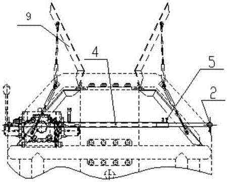
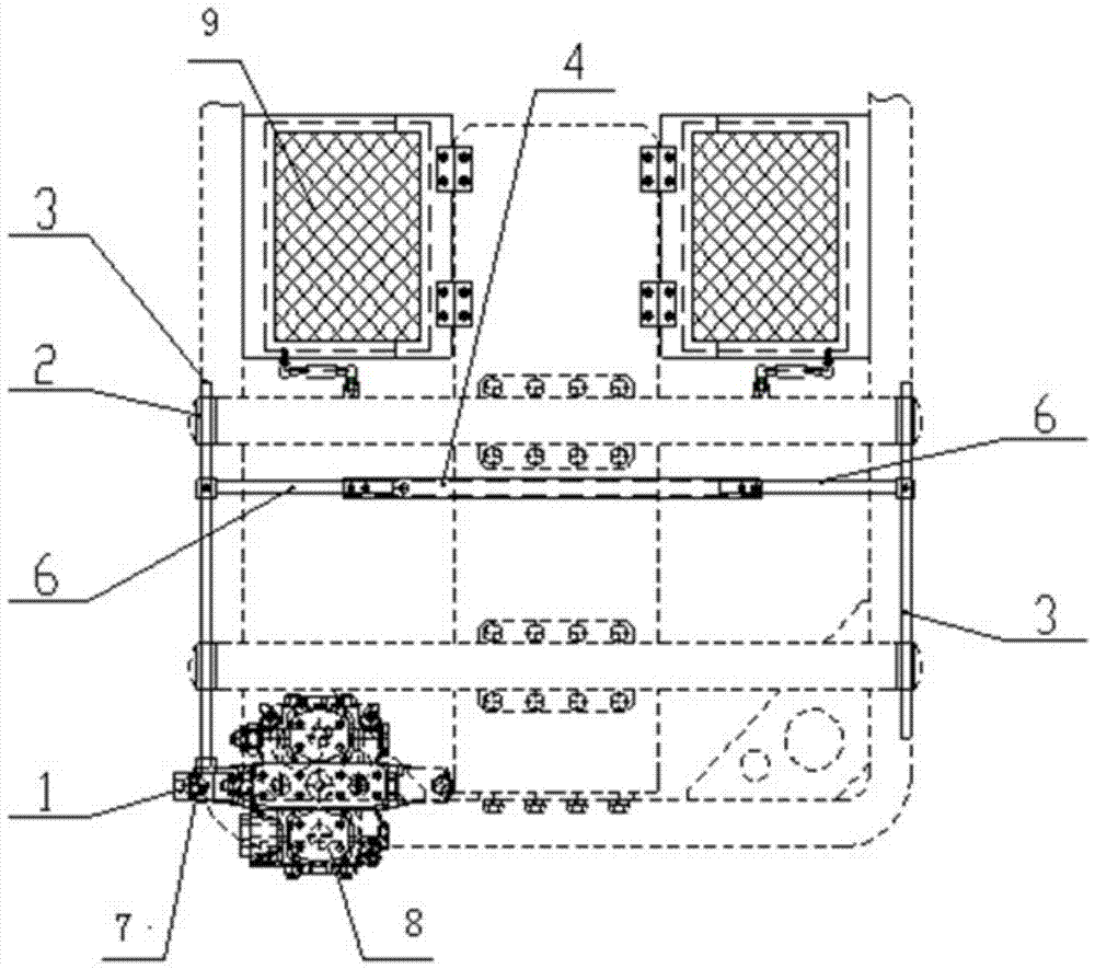
[0015] Such as figure 1 , 2 As shown, a safety interlock device for pipe end beveling machine consists of handle limit block (1), positioning sleeve (2), lock pin (3), connecting sleeve (4), screw (5 ), sliding sleeve connecting rods (6), one end of the two sliding sleeve connecting rods (6) is respectively connected to the two ends of the connecting sleeve (4) by screws, and the other end of the two sliding sleeve connecting rods (6) One end is respectively worn on the lock pins (3) on both sides, and the lock pins (3) on both sides are respectively worn on the positioning sleeve (2) fixed on the frame; the lock on the side of the cutter head rotary switch valve (8) One end of the pin (3) corresponds to the limit hole of the handle limit block (1) of the switch valve handle (7); the other end of the lock pin (3) on the side of the cutter head rotary switch valve (8) corresponds to the protective door (9) .

[0016] A safety interlocking method for a pipe end beveling machi...


PUM


Abstract

The invention relates to the technical field of auxiliary systems for pipe end beveling machines, and discloses a safety interlock method and interlocking device for pipe end beveling machines. The interlocking device consists of a handle limit block, a positioning sleeve, a lock Pin, connecting sleeve, screw, and sliding sleeve connecting rod. One end of the two sliding sleeve connecting rods is connected with the two ends of the connecting sleeve through screws, and the other ends of the two sliding sleeve connecting rods are respectively worn on both sides. On the lock pin, the lock pins on both sides are respectively worn on the positioning sleeve fixed on the frame; the end of the lock pin on the switch valve side of the cutter head is corresponding to the limit hole of the handle limit block of the switch valve handle; The other end of the lock pin on the disc rotary switch valve side corresponds to the protective door. The invention has the advantages of simple and reliable structure, convenient installation and adjustment, low production cost, can force on-site operators to operate the equipment according to the specifications, and greatly improves the safety of the equipment during operation.

Description

technical field [0001] The invention relates to the technical field of auxiliary systems of a pipe end face beveling machine, in particular to a safety interlock method and an interlocking device for a pipe end face beveling machine. Background technique [0002] The pipe end beveling machine generally cuts the end face of the pipe through the rotation of the cutter head to perform beveling operations. The cutter head rotates at a high speed, and the cut iron chips are easy to wrap around the cutter and rotate with the cutter head. Therefore, when the equipment rotates, There is a certain risk. Contents of the invention [0003] The purpose of the present invention is to overcome the deficiencies in the existing equipment, to provide a safety interlock method and interlock device for the pipe end face beveling machine, which can safely and reliably avoid the danger of injury when the equipment is working . [0004] In order to achieve the above-mentioned purpose of the i...

Claims


Application Information

Patent Timeline
Patent Type & Authority Patents(China)
IPC IPC(8): B23Q11/00
CPCB23Q11/08
Inventor 朱晓光朱品李建春
Owner LUOYANG DEPING TECH
Why Eureka
Try Eureka