Planar spiral microphone array

A microphone array and helical technology, applied in the field of microphone arrays, can solve the problems of affecting detection accuracy, large position error of array elements, and easy change of effective aperture.

Inactive Publication Date: 2010-10-13
INST OF ACOUSTICS CHINESE ACAD OF SCI
View PDF3 Cites 30 Cited by
  • Summary
  • Abstract
  • Description
  • Claims
  • Application Information

AI Technical Summary

Problems solved by technology

The unstable structure will lead to a large error in the position of the array element, making the eff

Method used


Image

  • Planar spiral microphone array
  • Planar spiral microphone array
  • Planar spiral microphone array

Examples


Example Embodiment

[0067] Example 1

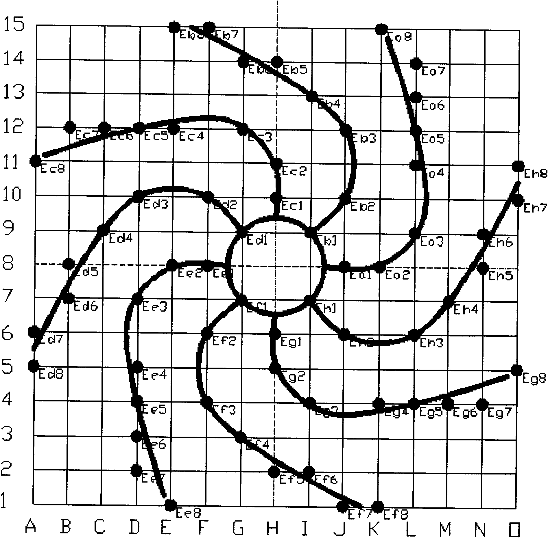
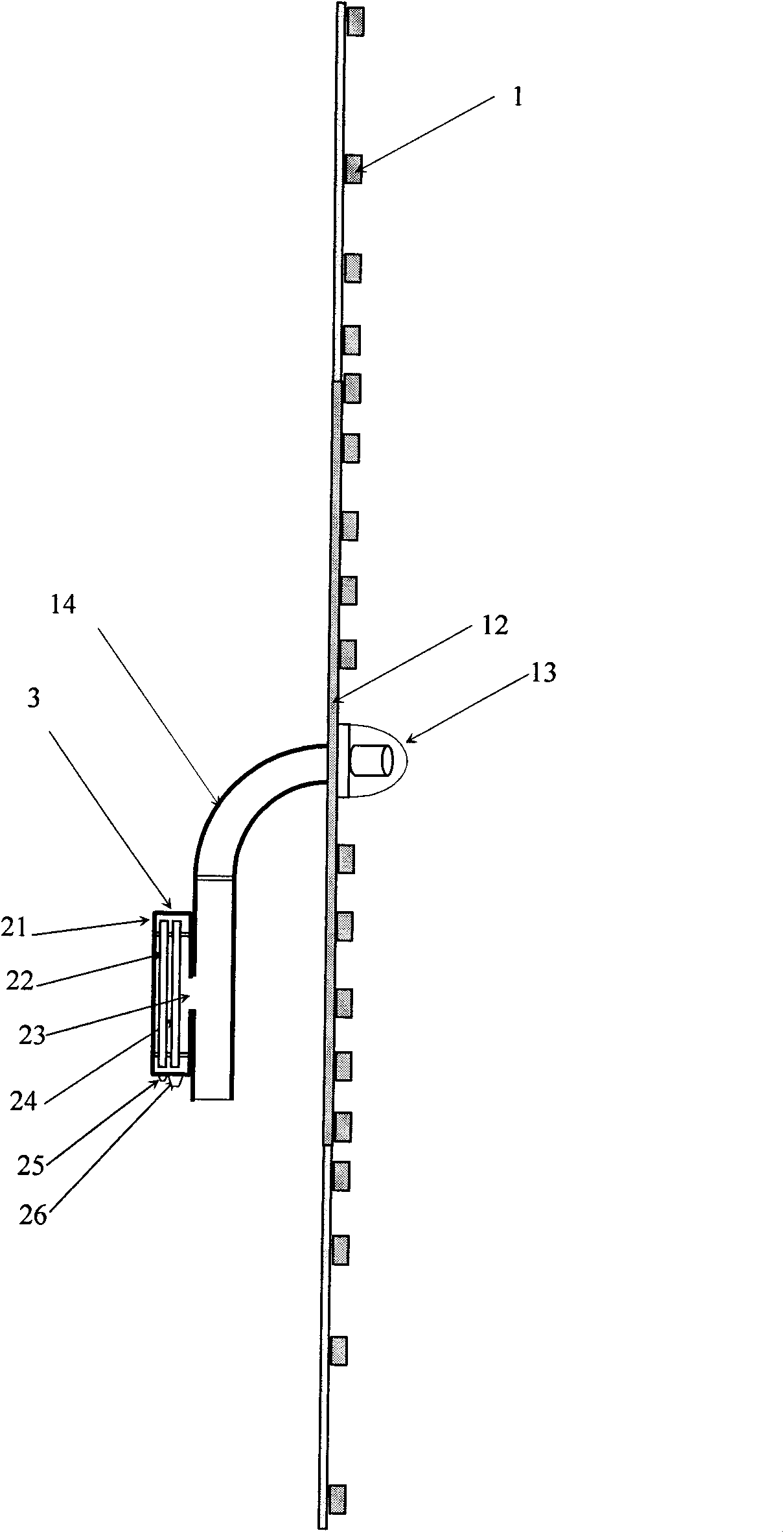
[0068] Such as Figure 10-13 As shown, this embodiment provides a planar spiral microphone array composed of a square array body part and four array folding parts. The planar spiral microphone array of this embodiment includes main components such as planar spiral array rigid spokes, support rods, microphones, cameras, and signal acquisition and processing instruments.

[0069] In this embodiment, a microphone mounting hole is designed at each position of the array element, and the mounting hole is fixedly connected to the preamplifier through the array element installation insulating sheath. The design of this mounting seat facilitates the installation of the microphone.

[0070] In order to cooperate with the planar spiral microphone array of this embodiment for data collection, a corresponding hub plug box and a signal conditioning and collection instrument box are also designed. The signal line of each element (ie microphone) is independently fixedly connecte...

Example Embodiment

[0078] Example 2

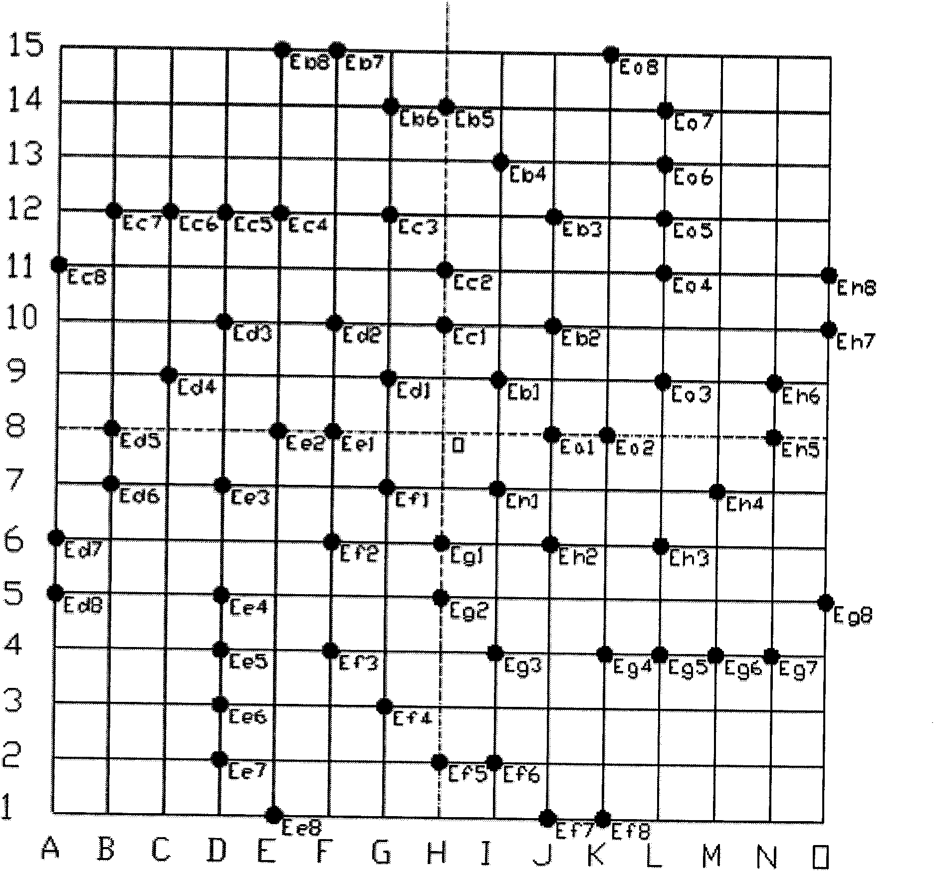
[0079] This embodiment is basically the same as Embodiment 1. The difference is that the structure of the array body part 12 and the array folding portion 11 of this embodiment is simpler, and is circular and spiral, such as Figure 14 with 15 Shown. This structure changes the number of spokes of the planar spiral microphone array, but the distribution position relationship of the array element sensor is exactly the same as that of Embodiment 1, that is, the array element coordinates are unchanged.

Example Embodiment

[0080] Example 3

[0081] Such as Figure 16 As shown, the plane spiral rigid support has a total of 64 nodes, and all nodes are distributed at a special coordinate. These nodes are located at selected nodes in the intersection of 21 lines evenly spaced in the horizontal direction and 21 lines evenly spaced in the vertical direction. The selected nodes are distributed on 8 spirals, each with 8 array elements. The normalized coordinates are shown in Table 4.

[0082] Table 4 (Spiral array coordinates of array elements distributed on 21×21 cross nodes)

[0083] Array element label

[0084] Array element label


PUM


Abstract

The invention relates to a planar spiral microphone array. The planar helix microphone array comprises an array camera, an array main body which are arranged at the center position and a plurality of microphones which are arranged on the array main body; the array main body is a plurality of planar spiral rigid spokes; the planar spiral microphone array is characterized in that: the microphones are distributed on cross nodes of n*n groined lines which are spaced uniformly in a plane, wherein n is an integral multiple of 15 or 21. The number of the planar spiral rigid spokes is 8, each rigid spoke is provided with 8 array elements, and the 64 array elements are distributed on the cross nodes of the 15*15 groined lines. The planar spiral microphone array has a simple and reliable structure,the number of support arms which are connected to each node is a few, influence on a sound field is less, and the detection precision is improved; the planar spiral microphone array adopts a fully rigid structure and is stable and reliable, so that an error which is caused by changes of an effective aperture because of flexible connection is avoided; and the planar spiral microphone array has theadvantages of multiple array element microphones, large information acquisition capacity, high positioning accuracy and wide positioning range.

Description

technical field [0001] The invention relates to a microphone array in the field of acoustic measurement, in particular, the invention relates to a planar spiral microphone array. Background technique [0002] The microphone array is an acoustic detection device that combines multiple microphones according to a certain geometric distribution. The device can detect multiple sound sources synchronously in combination with signal processing software, can measure the spatial information of the sound source, and can detect specific locations. The sound source performs signal enhancement and suppresses background interference processing, which can improve the equipment's ability to pick up the target sound, and can also be used to track the movement of the sound source. This device appears in most applications in the field of modern acoustic measurement, such as hearing aids, telephones Conference systems, computer terminal equipment, etc., are used to realize functions such as voi...

Claims


Application Information

Patent Timeline
IPC IPC(8): H04R1/20
Inventor 杨亦春滕鹏晓陈日林刘哲
Owner INST OF ACOUSTICS CHINESE ACAD OF SCI
Why Eureka
Try Eureka