
One-way isolated type metal-oxide-semiconductor filed-effect transistor (MOSFET) drive circuit

A drive circuit and isolation technology, applied in the field of power electronic drive applications, can solve the problems of increased loss of the drive circuit, slow MOSFET turn-on, lack of a level conversion circuit at the input end, etc., to achieve high integration, simple and reliable circuit structure, high performance stable effect

Inactive Publication Date: 2013-07-10
LG ELECTRONICS CHINA RANDD CENT SHANGHAI CO LTD
View PDF6 Cites 34 Cited by
  • Summary
  • Abstract
  • Description
  • Claims
  • Application Information

AI Technical Summary

Problems solved by technology

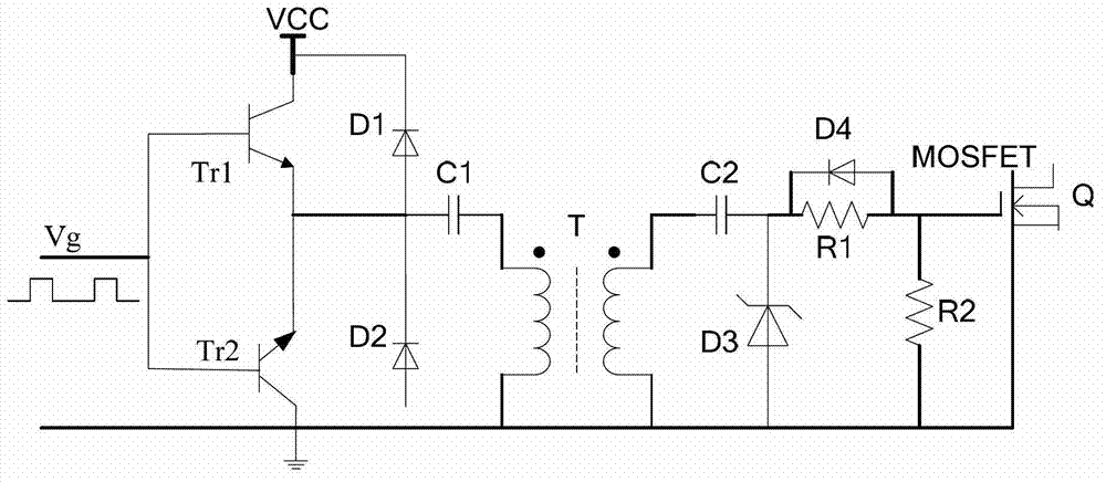
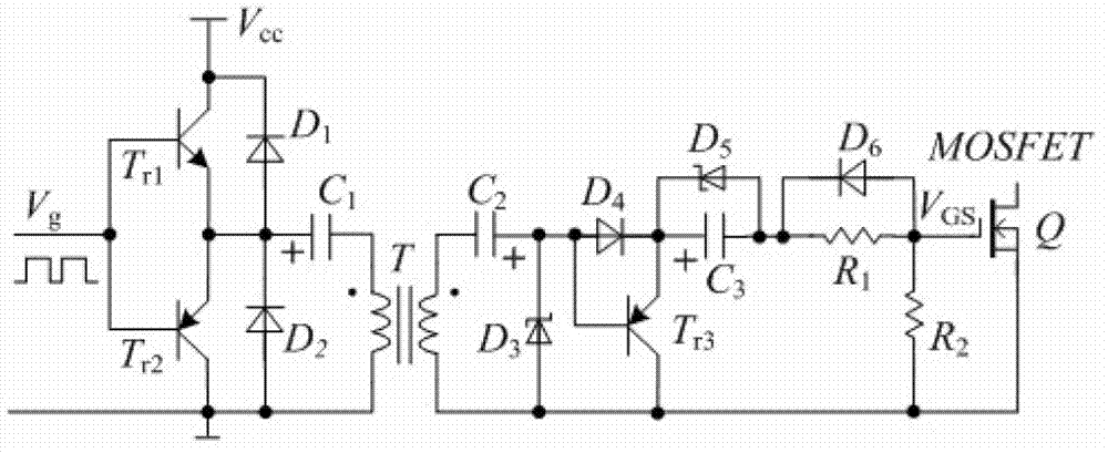
[0008] 1. The input end lacks a level conversion circuit, so that the PWM signal level must be equal to the drive power Vcc;
[0009] 2. Zener diode D3 will cause the PWM turn-on signal to come, the driving current mainly flows through the Zener diode D3 instead of the parasitic capacitance of the MOSFET, resulting in increased drive circuit loss, slow MOSFET turn-on, and the Miller capacitance effect is more prominent

Method used


Image

  • One-way isolated type metal-oxide-semiconductor filed-effect transistor (MOSFET) drive circuit
  • One-way isolated type metal-oxide-semiconductor filed-effect transistor (MOSFET) drive circuit
  • One-way isolated type metal-oxide-semiconductor filed-effect transistor (MOSFET) drive circuit

Examples


specific Embodiment 1

[0036] The single-channel isolated MOSFET driving circuit of the embodiment of the present invention has been successfully applied to electronic ballasts for high-intensity gas discharge lamps. For digitally controlled electronic ballasts that are widely used, the driving circuit adopts the circuit proposed by the present invention. Specific circuit such as Figure 4 shown. The level conversion and pulse drive circuit only need four low-power transistors and ordinary resistors and capacitors. Except for the pulse transformer, other components of the entire drive circuit are commonly used devices with strong versatility. The circuit structure is simple, low cost and high reliability. Through experiments, the circuit can still work reliably at a frequency of 500kHz, realizing a low-cost, high-reliability isolated drive scheme.

specific Embodiment 2

[0037] The single-channel isolated MOSFET drive circuit of the embodiment of the present invention is also used in the excitation converter of the electric locomotive motor. The rotor excitation converter adopts a single-channel Buck circuit, and its drive circuit is as follows: Figure 5 As shown, the working waveform is as Figure 6 shown. The level conversion circuit can be compatible with 3.3V and 5V PWM (or PFM) signal input by using a comparator, and has strong anti-interference ability. pull circuit drive. according to Figure 6 As shown in the working waveform, when the output duty ratio reaches 0.9, the driving circuit works stably and reliably. In addition to the pulse transformer, other components of the entire driving circuit are commonly used components with strong versatility, the circuit structure is simple, the cost is low and the reliability is high.

specific Embodiment 3

[0038] The single-channel isolated MOSFET driving circuit of the embodiment of the present invention has been successfully applied in the charging and discharging circuit of the storage battery. For the widely used bidirectional Buck-Boost charging and discharging circuit, the driving circuit adopts the circuit proposed by the present invention. The specific circuit is as follows Figure 7 shown. The circuit uses the integrated driver chip UCC27324 to realize the independent input and isolated drive of PWM-IN1 and PWM-IN2, and also realizes the level conversion function. The switch tube of the bidirectional Buck-Boost circuit to the ground is directly driven by UCC27324, including Both level shifting and power driving are done by it. The floating switching tube of the bidirectional Buck-Boost circuit is driven by a pulse transformer plus the related circuit of the present invention, wherein the pulse transformer is driven by UCC27324. The characteristic of the circuit is that...


PUM


Abstract

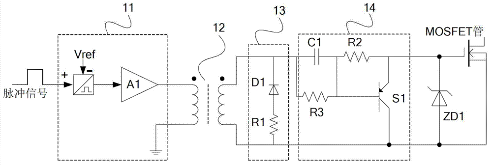
The invention discloses a one-way isolated type metal-oxide-semiconductor filed-effect transistor (MOSFET) drive circuit. The one-way isolated type MOSFET drive circuit comprises a level transformation and pulse drive circuit, a pulse transformer, a magnetic reset circuit and an acceleration turn-off circuit. The level transformation and pulse drive circuit is used for level transformation and power amplification on input pulse signals so as to drive the pulse transformer to work. The magnetic reset circuit is used for enabling the pulse transformer to carry out reliable magnetic reset. The acceleration turn-off circuit is used for accelerating turn-on and turn-off of a MOSFET tube, and comprises a capacitor, a second resistor, a third resistor and a PNP type triode. One end of the capacitor is connected with an auxiliary edge synonym end of the pulse transformer, the other end of the capacitor is connected with the second resistor, and the other end of the second resistor is connected with a grid electrode of the MOSFET tube. The third resistor is connected with the capacitor in parallel, a collector electrode of the PNP type triode is connected with an auxiliary edge non-synonym end of the pulse transformer, a base electrode of the PNP type triode and the capacitor are connected with one end of the second resistor, and an emitting electrode of the PNP type triode is connected with the grid electrode of the MOSFET tube.

Description

technical field [0001] The invention relates to the technical field of power electronics drive applications, in particular to a MOSFET drive circuit in a power management circuit, specifically a single-channel isolated MOSFET drive circuit. Background technique [0002] MOSFET is a voltage-controlled device with high input impedance and requires little static driving power. However, due to the parasitic capacitance between the poles, the drive circuit must be able to quickly charge / discharge its parasitic capacitance during turn-on and turn-off, especially in high-frequency applications. Therefore, the driving pulse should have a sufficiently steep rise and fall speed with a small delay. When it is turned on, it can provide a large enough instantaneous peak current, so that the turn-on delay and Miller plateau time are short enough to complete the charging and discharging of the input capacitor Ciss of the power tube within the required time; when it is turned off, it can p...

Claims


Application Information

Patent Timeline
Patent Type & Authority Applications(China)
IPC IPC(8): H02M1/08
Inventor 王议锋王成山车延博张轶强
Owner LG ELECTRONICS CHINA RANDD CENT SHANGHAI CO LTD
Learn More