
Blast furnace gas dehydrator

A blast furnace gas and dehydrator technology, applied in the field of dehydrators, can solve the problems of complicated filter screen cleaning and the like

Active Publication Date: 2016-03-02
湖南衡钢百达先锋能源科技有限公司
View PDF7 Cites 0 Cited by
  • Summary
  • Abstract
  • Description
  • Claims
  • Application Information

AI Technical Summary

Problems solved by technology

[0005] The present invention aims to provide a blast furnace gas dehydrator to solve the problem of complex cleaning of the filter screen of the blast furnace gas dehydrator in the prior art

Method used


Image

  • Blast furnace gas dehydrator
  • Blast furnace gas dehydrator
  • Blast furnace gas dehydrator

Examples


Embodiment Construction

[0023] It should be noted that, in the case of no conflict, the embodiments in the present application and the features in the embodiments can be combined with each other. The present invention will be described in detail below with reference to the accompanying drawings and examples.

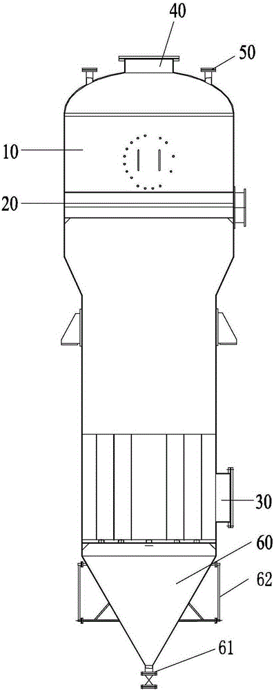
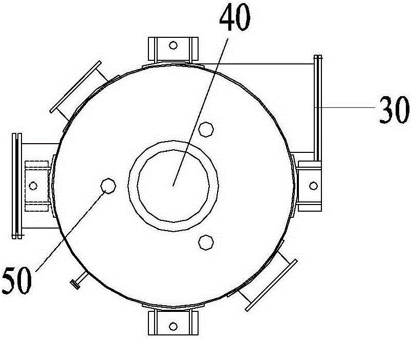
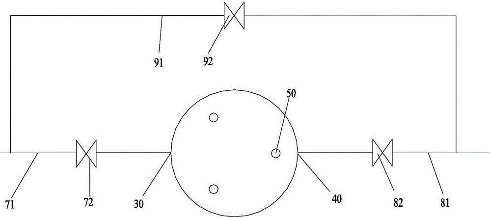
[0024] Such as figure 1 As shown, the blast furnace gas dehydrator of this embodiment includes a casing 10 and a filter screen 20 disposed in the casing 10 , the bottom of the casing 10 is provided with an air inlet 30 , and the top is provided with an air outlet 40 . Wherein, the air inlet 30 and the air outlet 40 are respectively located on two sides of the filter screen 20 . The blast furnace gas dehydrator also includes: a blowback port 50 , a blowback pipeline and a filter residue collection device 60 . Wherein, the blowback port 50 is arranged on the casing 10 and is located on the same side of the filter screen 20 as the air outlet 40 . The blowback pipeline is connected with the blow...


PUM


Abstract

The invention provides a blast furnace gas dehydrator. The blast furnace gas dehydrator comprises a shell body (10) and a filter mesh (20) arranged in the shell body (10), wherein a gas inlet (30) is formed in the bottom of the shell body (10), a gas outlet (40) is formed in the top of the shell body (10), and the gas inlet (30) and the gas outlet (40) are respectively located at the two sides of the filter mesh (20). The blast furnace gas dehydrator further comprises blowback openings (50), a blowback pipeline and a filter residue collection device (60), wherein the blowback openings (50) are formed in the shell body (10), and the blowback openings (50) and the gas outlet (40) are located at the same side of the filter mesh (20); the blowback pipeline is connected with the blowback openings (50); the filter residue collection device (60) is connected to the shell body (10), and the filter residue collection device (60) and the gas inlet (30) are located at the same side of the filter mesh (20). According to the blast furnace gas dehydrator provided by the invention, the problem in the prior art that the filter mesh of the blast furnace gas dehydrator is complicated to clean is solved effectively.

Description

technical field [0001] The invention relates to the technical field of dehydrators, in particular to a blast furnace gas dehydrator. Background technique [0002] Blast furnace gas is a by-product of iron-making blast furnace production. Because of its low calorific value, it is not easy to use directly. The nitrogen in it is separated by pressure swing adsorption, and the concentration of combustible components in it is increased, and it is directly used for heating furnace combustion. Very good economic and social benefits. [0003] Blast furnace gas contains dust, and after bag dust removal, it still contains 10mg / Nm 3 About dust (sometimes even greater than 10mg / Nm 3 ). The blast furnace gas is then sent to a dehydrator for further filtration to remove dust and moisture. [0004] In the process of purifying blast furnace gas, the capacity of the dehydrator to treat blast furnace gas is 66700Nm 3 / h, a large amount of dust enters the dehydrator every hour. Usually, ...

Claims


Application Information

Patent Timeline
IPC IPC(8): C21B5/06C10K1/00C10K1/02
CPCY02P10/20Y02P10/25
Inventor 刘光穆刘鹏
Owner 湖南衡钢百达先锋能源科技有限公司
Learn More