Method for connecting DTU equipment cabinet and switch cabinet

A connection method and switchgear technology, applied in the direction of busbar/line layout, etc., can solve the problems of cumbersome workload, unfavorable staff work, not easy to organize, etc., and achieve the effect of simple and convenient connection, clear and clear connection, and simple structure

Inactive Publication Date: 2014-03-12
STATE GRID CORP OF CHINA +3
View PDF0 Cites 1 Cited by
  • Summary
  • Abstract
  • Description
  • Claims
  • Application Information

AI Technical Summary

Problems solved by technology

[0002] At present, there are many connecting lines between the DTU cabinet and the switch cabinet in the power distribution terminal. When there are multiple lines, the control circuit cables and AC circuit cables of each switch cabinet need to be introduced into the DTU cabinet. The more lines, the more cables, the more It is not easy to be organized, which brings a serious and cumbersome workload when connecting the lines, which is not conducive to the work of the staff

Method used


Image

  • Method for connecting DTU equipment cabinet and switch cabinet

Examples


Embodiment 1

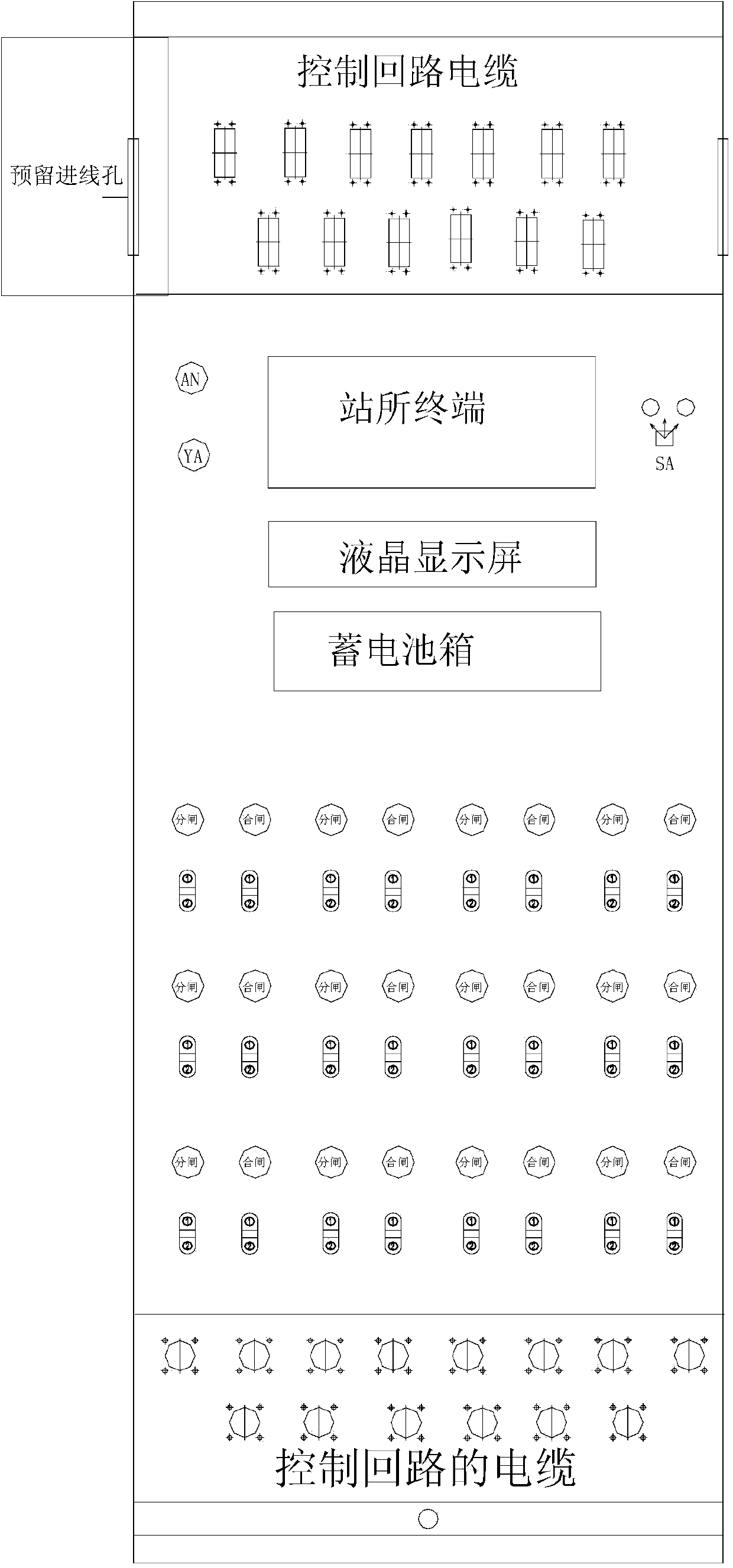
[0022] Embodiment one: if figure 1 As shown, the present invention includes a DTU cabinet and a switch cabinet, and the DTU cabinet and the switch cabinet are connected by cables, including the following steps:

[0023] 1) Comb the cables, divide the control loop cables and AC loop cables in each line, label the control loop cables and the AC loop cables of each line in sequence, and divide the control loop cables and the AC loop cables Split the above AC loop cable;

[0024] 2) Set the cable hole of the DTU cabinet, set the cable holes for the control circuit cable and the AC circuit cable on the top, bottom or left and right of the DTU cabinet respectively, and set a plurality of the upper and lower ends of the DTU cabinet respectively. A cable hole for the control loop cable and the AC loop cable;

[0025] 3) Set cable holes for the switch cabinet, set the cable holes for the control loop cable and the AC loop cable on the top, bottom or left and right of the switch cabin...

Embodiment approach 1

[0027] Embodiment 1, the cable hole of the control loop cable is set on the upper end of the DTU cabinet, the cable hole of the AC loop is set on the lower end of the DTU cabinet, and the cable hole of the control loop cable is set on the DTU cabinet. The upper end of the switch cabinet, the cable hole of the AC circuit is arranged at the lower end of the switch cabinet.

Embodiment approach 2

[0028] Embodiment 2, the cable hole of the control loop cable is set at the lower end of the DTU cabinet, the cable hole of the AC loop is set at the upper end of the DTU cabinet, and the cable hole of the control loop cable is set at the lower end of the DTU cabinet. The lower end of the switch cabinet, the cable hole of the AC circuit is arranged at the upper end of the switch cabinet.

[0029] To sum up, the divided and labeled cables are connected corresponding to the holes provided in the cabinet.


PUM


Abstract

The invention discloses a method for connecting a DTU equipment cabinet and a switch cabinet. According to the method, the DTU equipment cabinet and the switch cabinet are adopted and are connected through cables. Control loop cable and alternating current loop cable installing holes in the DTU equipment cabinet and the switch cabinet are respectively formed at the upper end and the lower end of the equipment cabinet, and all circuits can be clearly and definitely sorted for installation. The method has the advantages that the structure is simpler, during the installation of each circuit, all circuits can be clearly and definitely connected, and the connection is simpler and more convenient.

Description

technical field [0001] The invention relates to a connection method, in particular to a connection method between a DTU cabinet and a switch cabinet. Background technique [0002] At present, there are many connecting lines between the DTU cabinet and the switch cabinet in the power distribution terminal. When there are multiple lines, the control circuit cables and AC circuit cables of each switch cabinet need to be introduced into the DTU cabinet. The more lines, the more cables, the more It is not easy to be regular, which brings serious and tedious workload when connecting the lines, which is not conducive to the work of the staff. Contents of the invention [0003] The object of the present invention is to provide a connection method between a DTU cabinet and a switch cabinet in order to solve the above problems. [0004] The present invention achieves the above object through the following technical solutions: [0005] The present invention includes a DTU cabinet a...

Claims


Application Information

Patent Timeline
Patent Type & Authority Applications(China)
IPC IPC(8): H02B1/20
Inventor 杨建华郑贤舜黄佳佳周宗庚赵深戴瑞海林群柴谦益梁一晨杨振王化章丹阳郑圣吴旭光薛大立宓群超叶茜茜温积群
Owner STATE GRID CORP OF CHINA
Why Eureka
Try Eureka