led display and led control system

A technology of LED display and display, applied in static indicators, instruments, etc., can solve problems such as low refresh rate and large PCB area

Active Publication Date: 2016-08-10
LEYARD
View PDF6 Cites 0 Cited by
  • Summary
  • Abstract
  • Description
  • Claims
  • Application Information

AI Technical Summary

Problems solved by technology

[0010] Aiming at the problems of large PCB area occupied by the control circuit of the related art LED display and low refresh rate, no effective solution has been proposed at present. Therefore, the main purpose of the present invention is to provide an LED display and LED control system to solve the above problems. question

Method used


Image

  • led display and led control system
  • led display and led control system
  • led display and led control system

Examples


Embodiment 1

[0077] Figure 4 is a schematic structural view of an LED display according to Embodiment 1 of the present invention; Figures 5a to 5c It is a schematic diagram of the detailed structure of the LED display according to Embodiment 1 of the present invention. Such as Figure 4 , Figure 5a , 5b , 5c, the LED display includes: LED display panel 10; display drive circuit 30, including: switch circuit 31, drive circuit 33 and control circuit 35, wherein the first end of one of switch circuit 31 and drive circuit 33 Connect to the power terminal of the power supply equipment, the first end of the other is connected to the ground terminal of the power supply equipment; the second end of one of the switch circuit 31 and the drive circuit 33 is connected to the anode of the LED display panel 10, and the second end of the other terminal is connected to the cathode of the LED display panel 10; the control circuit 35 includes: a power supply control circuit 351 and a driver 353, wher...

Embodiment 2

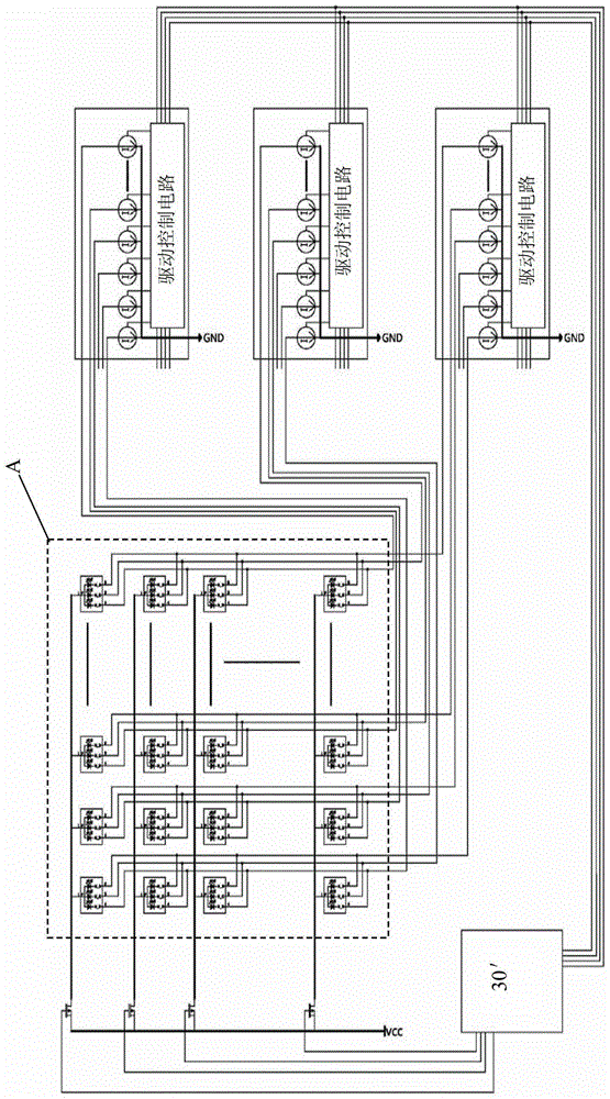
[0112] Figures 6a to 6c is a schematic structural diagram of an LED display according to Embodiment 2 of the present invention. Such as Figure 6a As shown, the field effect tube in the LED display can also be an N-MOS tube, and the LED display panel 10 can include LED particles in M ​​rows and N columns, and each LED particle includes a red light tube, a green light tube and a blue light tube respectively. tube, wherein the cathode of the red light tube, the cathode of the green light tube and the cathode of the blue light tube in the i-th LED particle in each row are connected in parallel to the i-th node, each node in each row is connected in parallel, respectively The drain of a corresponding N-MOS tube in the switch circuit 31 is connected; the anodes of the red light tubes of the LED particles in each column are respectively connected in parallel, as a connecting terminal of the anode of the LED display panel 10, respectively connected to the first constant The second...

Embodiment 3 4

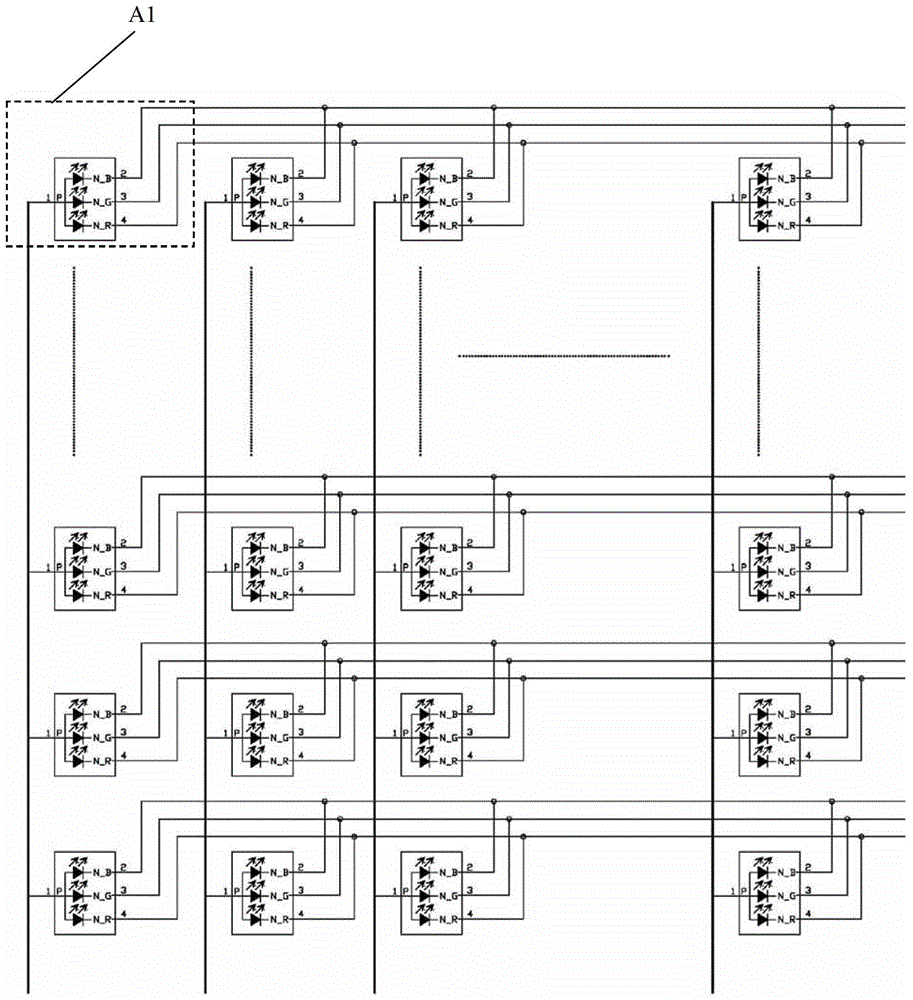
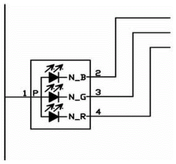
[0118] Figure 7a to Figure 7e is a schematic structural diagram of an LED display according to Embodiment 3 of the present invention; Figure 8a to Figure 8c is a schematic structural diagram of an LED display according to Embodiment 4 of the present invention. Such as Figure 7b and Figure 8b Shown are two implementations Figure 7a F covered by the dotted line and Figure 8a Partial enlarged view of H covered by the dotted line in the middle, Figure 7c The three primary color light-emitting diodes in the LED particles are directly integrated on the LED particles, while Figure 8c The three primary color light-emitting diodes in the middle LED particle are respectively packaged and integrated into the LED particle. In addition, the circuit connection relationship of the two implementations may be the same. in, Figure 7c The anode of each LED particle has 3 pins, respectively 1, 2, 3, corresponding to the anode of the internal R / G / B primary color light-emitting diod...


PUM


Abstract

The invention discloses an LED display and an LED control system. Wherein, the display includes: an LED display panel; a display driving circuit, including: a switch circuit, a drive circuit and a control circuit, wherein, the first end of one of the switch circuit and the drive circuit is connected to the power supply end of the power supply device, and the other The first end is connected to the ground terminal of the power supply device; the second end of one of the switch circuit and the driving circuit is connected to the anode of the LED display panel, and the second end of the other is connected to the cathode of the LED display panel; the control circuit includes: A power supply control circuit and a drive control circuit, wherein the power supply control circuit is connected to the third terminal of the switch circuit through a power supply control port; the drive control circuit controls the turn-on or cut-off of the drive circuit. Through the present invention, the switch circuit, the drive circuit and the control circuit are integrated into the display drive circuit, so that the control circuit of the LED display occupies a small area of ​​the panel, is simple in design and has a high refresh rate.

Description

technical field [0001] The invention relates to the field of LED control, in particular to an LED display and an LED control system. Background technique [0002] The current design of the LED display unit board adopts the way that LED, P-MOS tube, and LED driving circuit are placed separately. Such as Figure 1b As shown: the LED particles in the picture are four-legged R / G / B common anode three-in-one LED, 1 leg is the common anode, 2 / 3 / 4 are the cathodes of the B / G / R three-color LED; external display control Logic circuit, one of its control ports is a constant current control signal output port, and the other is a power supply control port. The two cooperate with each other to realize the LED array display work. [0003] Figures 1a to 1b It is a schematic diagram of the discrete placement of the LED drive circuit of the LED particles with three yangs in one in the prior art. Such as Figure 1a As shown, the LED drive circuit includes three logic circuits and their co...

Claims


Application Information

Patent Timeline
Patent Type & Authority Patents(China)
IPC IPC(8): G09G3/32
CPCG09G2300/0426G09G2310/0278G09G3/32G09G2310/061G09G2330/021G09G2330/028G09G2310/0264G09G2300/0452G09G3/3225G09G2310/08G09G2320/0252
Inventor 卢长军刘志勇
Owner LEYARD
Why Eureka
Try Eureka