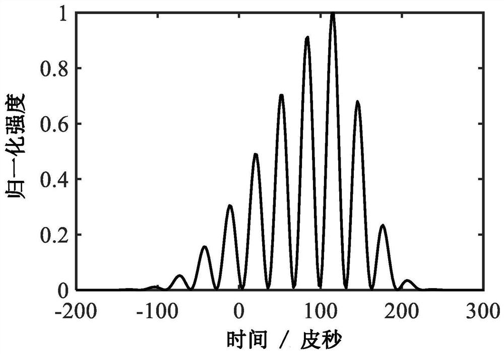
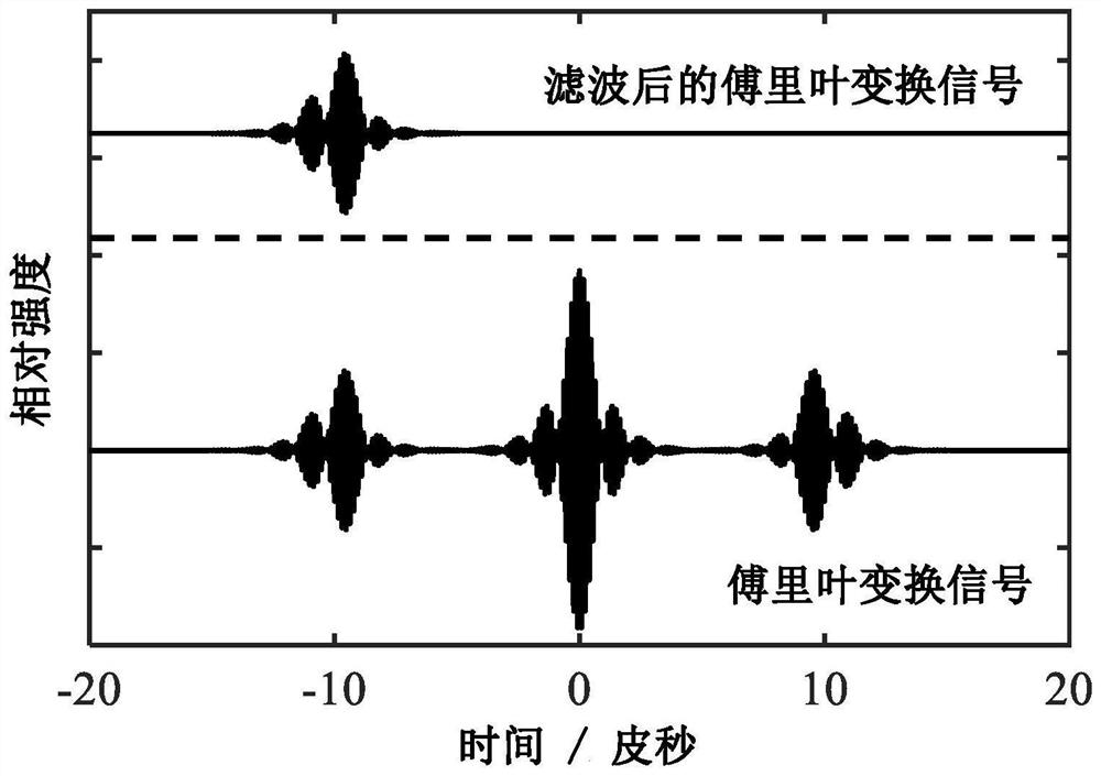
A method and system for real-time measurement of polarization state of vector ultrafast optical signal
A real-time measurement and optical signal technology, applied in the direction of measuring the polarization of light, optical radiation measurement, measuring devices, etc., can solve the problems of inability to analyze the polarization state evolution of optical signals, narrow response bandwidth, low refresh rate, etc., and achieve fast and effective technology means to improve the effect of response
Active Publication Date: 2021-08-10
SOUTH CHINA UNIV OF TECH
View PDF0 Cites 0 Cited by
- Summary
- Abstract
- Description
- Claims
- Application Information
AI Technical Summary
Problems solved by technology
[0003] At present, the polarization state analysis and measurement methods of vector ultrafast optical signals mainly include: 1) commercial polarization measuring instruments, which are generally not designed for large bandwidth vector ultrafast optical signals, due to the limited mechanical Rotation speed and applicable spectral bandwidth lead to low refresh rate and narrow response bandwidth; 2) Real-time measurement method of vector ultrafast optical signal based on dispersion Fourier transform. Recently, M. Liu et al. The frequency domain information of the signal (Liu M.etal.Dynamic trapping of a polarization rotation vector soliton in a fiberlaser.Optics Letters,2017,42(2):330-333), but the polarization of the optical signal cannot be analyzed due to the lack of relative phase data state evolution
Method used
View moreImage
Smart ImageViewing Examples
Examples
Embodiment
[0058] A vector ultrafast optical signal polarization state real-time measurement system, such as figure 1 As shown, it includes a dispersion element 1, an optical amplifier 2, a polarization beam splitting element 3, a polarization control element 4, an optical delay line 5, an optical coupler 6, a polarization-dependent element 7 and a high-speed signal acquisition component 8;
Login to View More PUM
 Abstract
The invention discloses a method and system for real-time measurement of the polarization state of a vector ultrafast optical signal. The method is as follows: the vector ultrafast optical signal to be measured is subjected to time-stretching time-frequency conversion through a dispersive element, and then the optical power attenuation introduced by the dispersive element is compensated through an optical amplifier to obtain an amplified optical signal, which is divided into Two optical signals whose polarization directions are orthogonal to each other, one optical signal rotates the optical polarization direction by 90 degrees through the polarization control element, and the other optical signal passes through the optical delay line to ensure that the optical paths of the two optical signals are close enough, and then the optical coupling is used to The device combines two optical signals and passes through polarization-related components to obtain an optical signal with a single polarization direction; the real-time intensity information of the processed optical signal is recorded in real time through a high-speed signal acquisition component, and the vector ultrafast light to be measured is obtained through Fourier algorithm The polarization state Stokes parameter of the signal. The invention can realize the polarization state analysis of the vector optical signal with a high refresh rate, and measure the Stokes parameter of the polarization state in real time.
Description
technical field [0001] The invention relates to the field of ultrafast signal measurement, in particular to a method and system for real-time measurement of the polarization state of a vector ultrafast optical signal. Background technique [0002] Ultrafast optical signals propagating in birefringent media will evolve vector characteristics due to cross-phase modulation, forming vector solitons. Therefore, in birefringent media, typically such as single-mode, polarization-maintaining fiber lasers and amplifiers, pulses usually exist in the form of vector solitons, accompanied by regular or irregular polarization state evolution. The polarization state stability is one of the important parameters to ensure the laser system, and the analysis of the polarization state of the vector ultrafast optical signal is also particularly critical. [0003] At present, the polarization state analysis and measurement methods of vector ultrafast optical signals mainly include: 1) commercial...
Claims
Login to View More Application Information
Patent Timeline
 Patent Type & Authority Patents(China)
IPC IPC(8): G01J4/04
CPCG01J4/04
Inventor 杨中民林巍文晓晓韦小明
Owner SOUTH CHINA UNIV OF TECH
Features
- R&D
- Intellectual Property
- Life Sciences
- Materials
- Tech Scout
- Unparalleled Data Quality
- Higher Quality Content
- 60% Fewer Hallucinations
Learn More Browse by: Latest US Patents, China's latest patents, Technical Efficacy Thesaurus, Application Domain, Technology Topic, Popular Technical Reports.
© 2025 PatSnap. All rights reserved.Legal|Privacy policy|Modern Slavery Act Transparency Statement|Sitemap|About US| Contact US: help@patsnap.com


