Radar alarm safety fence

A security fence and radar technology, applied to alarms, anti-theft alarms, instruments, etc., can solve the problems of inconsistent ground height, difficulty in aligning infrared emitting devices and infrared receiving devices, and taking a long time to achieve fearless The effect of ground height, improved radar scanning accuracy, and clear connection relationship

Inactive Publication Date: 2020-04-28
LUOHE POWER SUPPLY OF HENAN ELECTRIC POWER CORP
View PDF10 Cites 0 Cited by
  • Summary
  • Abstract
  • Description
  • Claims
  • Application Information

AI Technical Summary

Problems solved by technology

However, the voice alarm fence of the infrared power facility also has certain deficiencies. For example, when laying the safety fence, the ground level is inconsistent, and the infrared emitting device and the infrared receiving device are not easy to align, which will take a long time

Method used


Image

  • Radar alarm safety fence
  • Radar alarm safety fence
  • Radar alarm safety fence

Examples


specific Embodiment 1

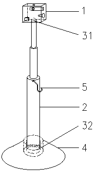
[0032] Specific embodiment 1: as figure 1 , figure 2 with image 3 shown.

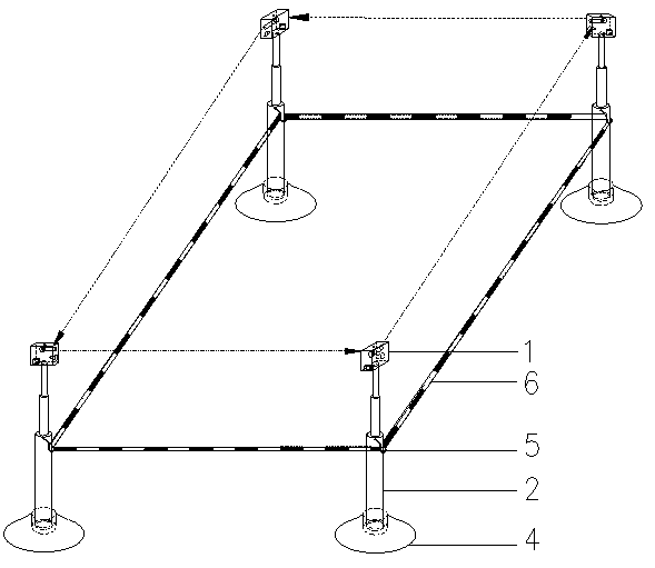
[0033] A radar alarm safety fence includes an alarm device 1, a support rod 2, a support rod interface 3, a base 4, a hanging ring 5, and a warning belt 6.

[0034] The bottom of the alarm device 1 is provided with a support rod interface I31, which is movably connected with the top of the support rod 2 through intermeshing threads; the base 4 is provided with a support rod interface II32, which is movably connected with the bottom end of the support rod 2 through intermeshing threads. The support rod 2 is a telescopic rod, and the upper end of the outer tube of the support rod 2 is bolted to fix the hanging ring 5. The hanging ring 5 is used to connect the warning belt 6 to facilitate the connection of the warning belt 6 and the supporting rod 2. The warning belt 6 passes through the hanging ring 5. Connect the installed alarm device 1, the support rod 2 and the base 4 to form a closed fence.

[...

specific Embodiment 2

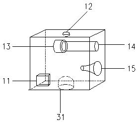
[0049] Such as Figure 4 As shown, the structure of this embodiment is basically the same as that of the specific embodiment 1, and the difference is that the battery 11 of the alarm device 1 is a solar rechargeable battery, and the battery 11 is electrically connected to the solar panel 16 and sealed with the microcontroller 17. Together, the solar panel 16 charges the battery 11, and the battery 11 supplies power to other electrical appliances. It is energy-saving and environmentally friendly. It does not require additional power supply or recharging after use. It is easy to install and use, and is especially suitable for long-term maintenance or temporary construction on the road.

[0050] Described alarm device 1 comprises battery 11, switch 12, radar launcher 13, parallel tube 14, alarm horn 15, solar panel 16, microcontroller 17, and described battery 11 is a solar rechargeable battery, battery 11 and solar panel 16 is electrically connected and sealed together with the ...

specific Embodiment 3

[0052] Such as Figure 5 As shown, the structure of the present embodiment is basically the same as that of the specific embodiment 1, and the difference is that the radar transmitter 13 of the alarm device 1 adopts a microwave special-purpose microprocessor 18 to control its detection range and distance, and the microprocessor 18 and the battery 11. The switch 12, the radar emitter 13 and the alarm horn 15 are electrically connected. The microprocessor 18 receives the signal from the switch 12 and starts to work, drives the radar emitter 13 to detect obstacles, and controls the alarm horn 15 to work after detecting the obstacle. The use of the microprocessor 18 not only increases the detection sensitivity, but also works very reliably, with an extremely low false alarm rate, and can work stably in the temperature range of -25 to +45 degrees. For weaker interference signals, such as small animals, it is far away The interference caused by shaking trees, high-frequency communic...


PUM


Abstract

The invention, which belongs to the field of electronic protection alarm equipment, particularly relates to a radar alarm safety fence comprising a warning device, a supporting rod, a supporting rod connector, a base, a hanging ring and a warning tape. The warning device is movably connected with the top end of the supporting rod through the supporting rod connector based on threads, the base is movably connected with the bottom end of the supporting rod through the supporting rod connector based on threads, the hanging ring is arranged on the supporting rod, the warning tape is connected withthe installed warning device, and the supporting rod and the base form a safety fence. The radar alarm safety fence is simple in structure, flexible to use, reliable in performance, convenient to install, low in requirement for the ground and strong in radar signal; all on-site personnel are reminded through alarm, so that hidden danger of the personnel in work is eliminated, and high safety is guaranteed.

Description

technical field [0001] The invention belongs to the field of electronic protection and alarm equipment, and in particular relates to a radar alarm safety fence. Background technique [0002] When the equipment in the substation needs to be overhauled, or when high-voltage tests need to be performed, in order to ensure the safety of the staff and prevent misoperation caused by accidental contact with the equipment, the work area is usually enclosed. The staff work inside the work area, and the outside is the high-voltage equipment area. When the staff are working in the work area, some staff with weak safety awareness often cross the fence due to habitual violations. Outside the fence is the high-voltage equipment area. If they are not reminded in time, they may be in danger of electric shock or touch the operating equipment by mistake. pose a serious danger. At the same time, other staff on site may not notice the above-mentioned violations when they are concentrating on th...

Claims


Application Information

Patent Timeline
IPC IPC(8): G08B13/181G08B13/183
CPCG08B13/181G08B13/183
Inventor 李亮赵永浩李幸赵永刚曹聪刘海燕郭腾举王永丽王永祥李培军宋小兵马永泽谢雄超
Owner LUOHE POWER SUPPLY OF HENAN ELECTRIC POWER CORP
Why Eureka
Try Eureka