hidden door suction
A concealed, door-sucking technology, applied in buildings, building fastening devices, and wing fan fastening devices, etc., can solve problems such as poor safety, and achieve the effect of reducing production costs, ensuring safety, and being easy to industrialize production.
- Summary
- Abstract
- Description
- Claims
- Application Information
AI Technical Summary
Problems solved by technology
Method used
Image
Examples
Embodiment 1
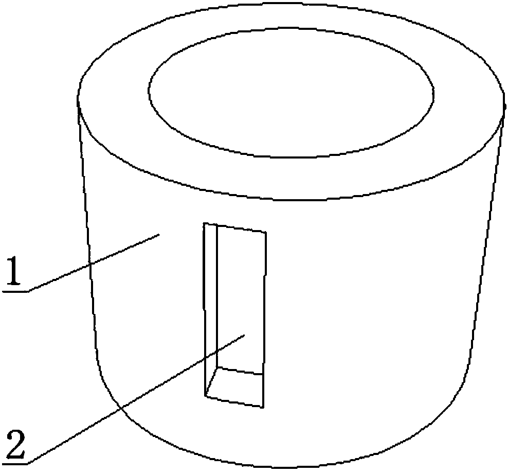
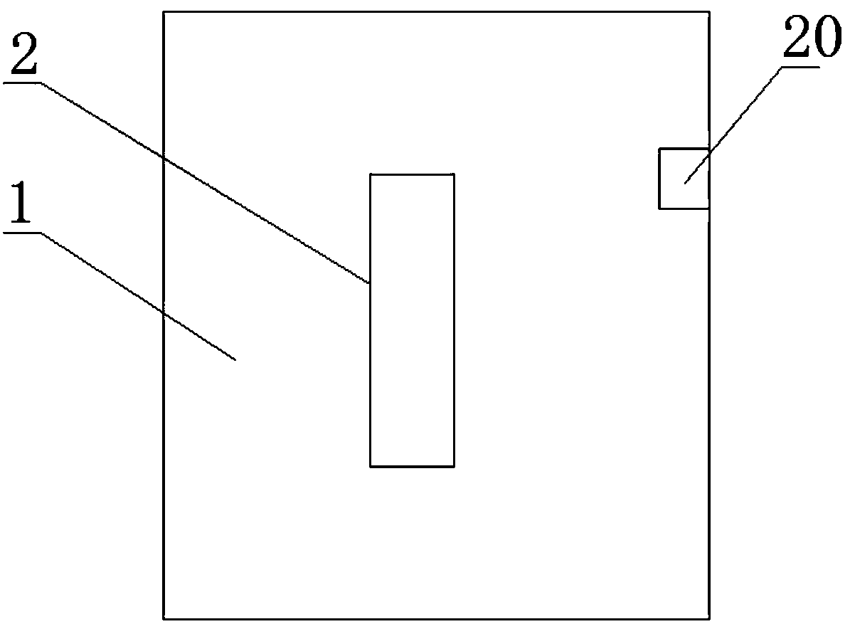
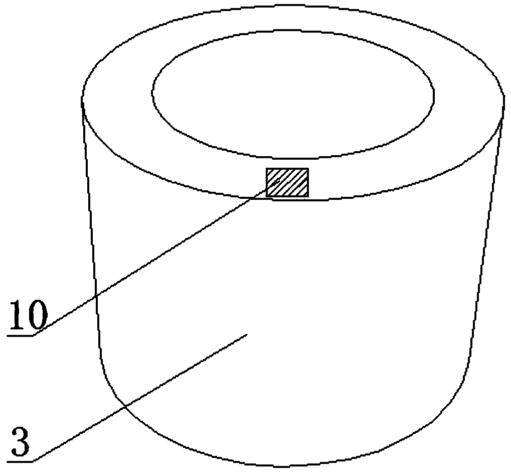
[0053] Such as Figure 1-10 As shown in any figure, the hidden door stopper includes a top cap 1, a spring 5, a bottom cylinder 3, a fixing device and a limiting device. The sleeve and the fixing device are provided with a pair of fixed cylinders 4 and a card slot 2. The fixed cylinders 4 are installed on the side wall of the bottom cylinder 3 through threads. The fixed cylinders 4 are vertical and protrude from the inner side wall of the bottom cylinder 3. The fixed cylinders 4 The outer wall of the fixed end of the fixed end is provided with an external thread, the outer wall of the engaging end of the fixed cylinder 4 is set as a smooth wall surface, and the slot 2 is set as a rectangular groove structure with the sealing end surface of the top cap 1 as the base surface, and the two slots 2 It is arranged symmetrically on the two outer walls of the top cap 1. The inner diameter of the bottom cylinder 3 is slightly larger than the outer diameter of the top cap 1. The spring ...
Embodiment 2
[0062] On the basis of Example 1, different from Example 1, such as Figure 14 , 15 As shown, the limiting device includes a pressing block 10, a limiting block 16, a spring a15, a spring b11, a horizontal connecting rod 13, a vertical connecting rod 19 and a disc 18, and the disc 18 is embedded in the bottom along the radial direction. In the side wall of the cylinder 3, a rotating shaft 17 is arranged at the center of the turntable, a groove a14 is arranged on the inner side wall of the bottom cylinder 3, a limit block 16 is embedded in the groove a14, and a concave groove is arranged on the upper end surface of the bottom cylinder 3. Groove b12, the pressing block 10 is set in the groove b12, one end of the horizontal connecting rod 13 and the vertical connecting rod 19 are respectively arranged on the disc 18 along the horizontal direction and the vertical direction, and the other end of the horizontal connecting rod 13 and the limit The block 16 is connected, the other e...
Embodiment 3
[0076] On the basis of Example 1, different from Example 1, such as Figure 12 As shown, the hidden door stopper includes a top cap 1, a spring 5, a bottom cylinder 3, a fixing device and a limit device. The part below the upper end surface of the groove 2 is set as a cylindrical structure that cooperates with the inner wall of the bottom cylinder 3; the bottom cylinder 3 is set as a hollow cylindrical sleeve with one end closed and the other open. The cylinder 4 is installed on the side wall of the top cap 1 through threads, the fixed cylinder 4 is vertical and protrudes from the inner wall of the top cap 1, and the outer wall of the fixed end of the fixed cylinder 4 is provided with external threads, and the fastening of the fixed cylinder 4 The outer side wall of the end is set as a smooth wall surface, and the card groove 2 is set as a rectangular groove structure with the sealing end surface of the bottom cylinder 3 as the base surface. The opening end of the top cap 1 i...
PUM
 Abstract
Description
Claims
Application Information
 - R&D
- Intellectual Property
- Life Sciences
- Materials
- Tech Scout
- Unparalleled Data Quality
- Higher Quality Content
- 60% Fewer Hallucinations
Browse by: Latest US Patents, China's latest patents, Technical Efficacy Thesaurus, Application Domain, Technology Topic, Popular Technical Reports.
© 2025 PatSnap. All rights reserved.Legal|Privacy policy|Modern Slavery Act Transparency Statement|Sitemap|About US| Contact US: help@patsnap.com


