
Method for detecting a triggering of a security device

A safety device and safety technology, applied in the direction of electrical devices, measuring devices, battery/fuel cell control devices, etc., can solve the problem of costing electronic equipment components

Active Publication Date: 2014-03-12
ROBERT BOSCH GMBH +1
View PDF6 Cites 9 Cited by
  • Summary
  • Abstract
  • Description
  • Claims
  • Application Information

AI Technical Summary

Problems solved by technology

The electronic components used can only be protected against such loads at great expense

Method used


Image

  • Method for detecting a triggering of a security device
  • Method for detecting a triggering of a security device
  • Method for detecting a triggering of a security device

Examples


Embodiment Construction

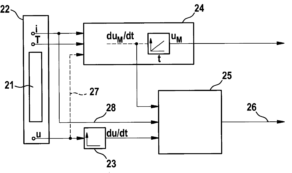
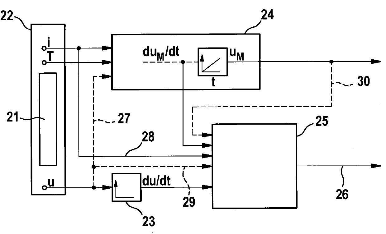
[0015] figure 1 A block diagram of battery state detection according to a first embodiment of the method according to the invention is shown. The safety device 21 is integrated in the battery cell 22 and short-circuits the battery cell 22 in the event of a safety hazard, in particular if the internal pressure of the battery cell 22 increases or is mechanically deformed. The voltage u of the battery cell 22 is continuously measured in the detection unit 23 and the actual change du / dt of the voltage over time is determined therefrom. At the same time, the expected time-dependent change du of the voltage is determined in the model unit 24 M / dt. This is achieved by supplying the battery current i and the battery temperature T to the model unit 24 . From this, the model unit 24 calculates the voltage u of the battery unit 22 M The expected change over time of and its rate of change with respect to time du M / dt. In particular, the model unit 24 is embodied as an observation ...


PUM


Abstract

The invention relates to a method for detecting a triggering of a security device (21). Said security device (21) is associated with a battery cell (22) and is triggered if a security-critical situation is present in the battery cell (22). Initially an actual time path of a parameter of the battery cell (23) is detected. At the same time, an expected time path of the parameter is determined, in particular using a model (24). Then, the actual time path is compared with the expected time path of the parameter (25). Finally, based on the comparison, it is determined whether to trigger the security device (21) or not.

Description

technical field [0001] The invention relates to a method for detecting triggering of a safety device associated with a battery unit, and to a battery management unit in which the method according to the invention can be carried out. Background technique [0002] Battery systems include rechargeable electrical energy storage devices that are widely used in portable consumer devices and other applications, such as in vehicles that are partially or completely electrically powered. In automotive applications, battery systems and especially lithium-ion battery systems are considered a key technology for the electrification of the drive system of a vehicle. The battery system, in particular a lithium-ion battery system, can be constructed modularly according to the application specification and usually includes a number of battery cells electrically connected in series or in parallel. [0003] An important aspect here for the successful establishment of this technology is the ope...

Claims


Application Information

Patent Timeline
Patent Type & Authority Applications(China)
IPC IPC(8): H01M2/34H01M10/44H01M10/48G01R19/165H01M50/574
CPCY02E60/12H01M10/443G01R31/3651H01M2/348H01M10/425H01M10/486G01R31/3627H01M2/34H01M10/48H01M10/44G01R31/367H01M50/581H01M50/574B60L3/0046B60L58/10Y02T10/70Y02E60/10G01R31/385
Inventor H·芬克
Owner ROBERT BOSCH GMBH
Learn More