Jet array-type aeration device

An oxygen-enhancing device and jet array technology, applied in the directions of fluid mixers, transportation and packaging, mixers, etc., can solve the problems of water exchange, high energy consumption, short oxygen dissolution time, long oxygen supply pipelines, etc. Better oxygenation effect

Active Publication Date: 2014-03-19
SOLIS HIGHT TECH INC SHENZHEN
View PDF6 Cites 1 Cited by
  • Summary
  • Abstract
  • Description
  • Claims
  • Application Information

AI Technical Summary

Problems solved by technology

The microporous aeration aerator uses a fan to inject air into the water to dissolve oxygen. Although the effect has been improved, a long oxygen supply pipeline must be laid above and below the water.
When the air bubbles generated by the aeration tube infiltrate into the water body in a vertical form, the buoyancy force they receive is relatively large, resulting in a short time for the residual oxygen to dissolve in the water body. Since the existing microporous aeration aerators are all fixed at the bottom of the water container, It is difficult to push air and water to a wider range, and it is also impossible to realize large-scale water communication between the upper and lower layers of the water body, and the energy consumption is high

Method used


Image

  • Jet array-type aeration device
  • Jet array-type aeration device
  • Jet array-type aeration device

Examples


Embodiment Construction

[0018] The application of the present invention will be described in detail below in conjunction with the accompanying drawings.

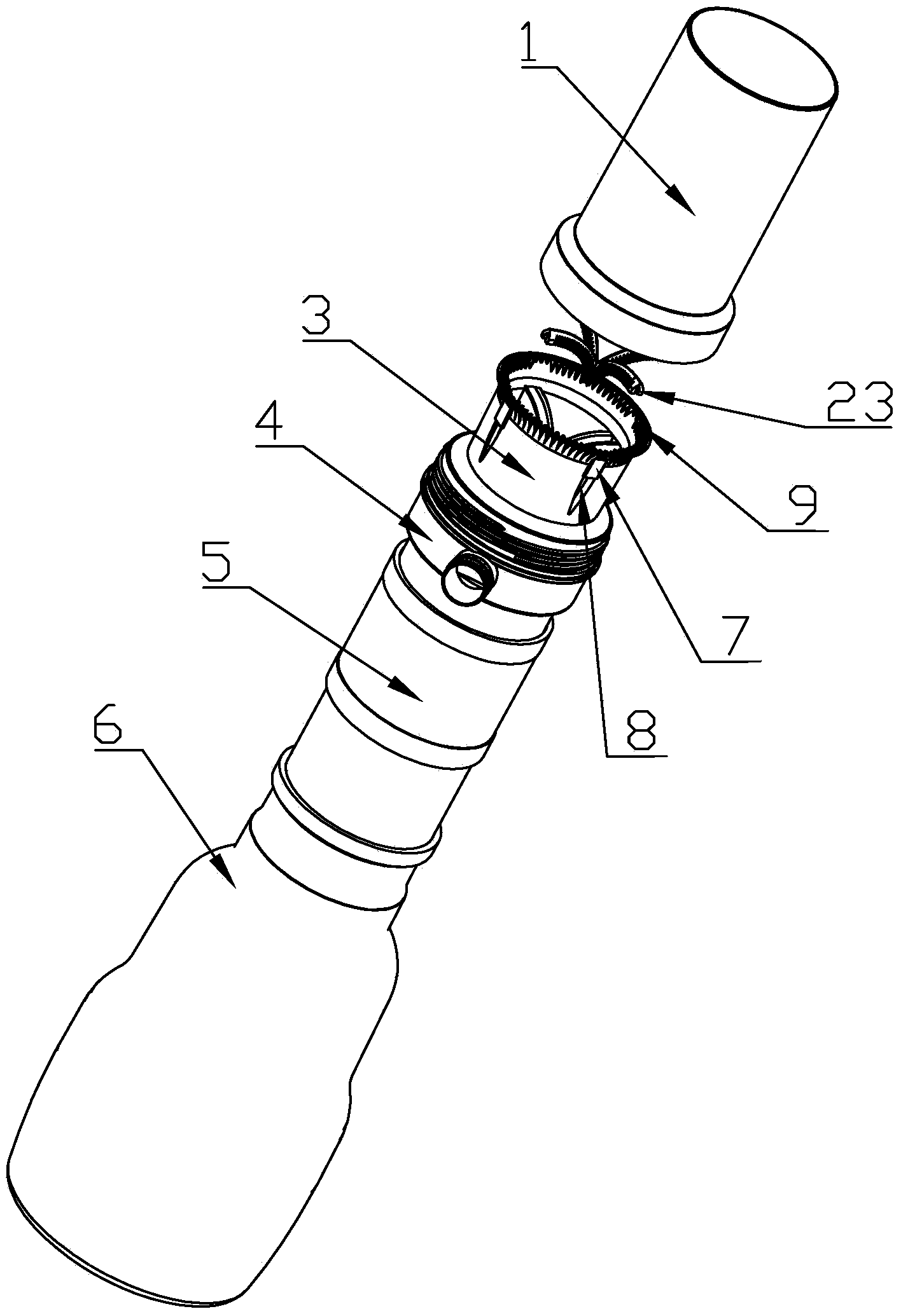
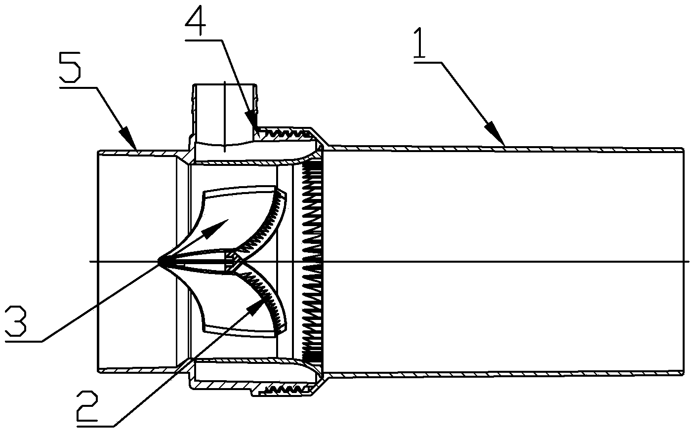
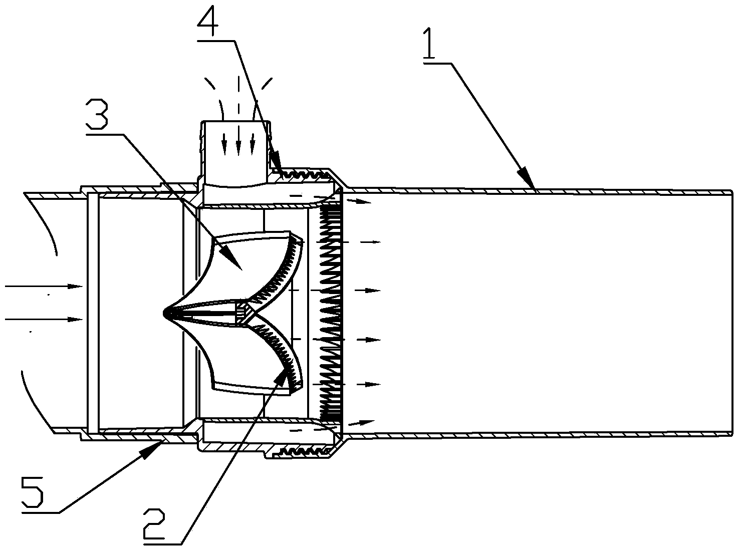
[0019] refer to Figure 1 to Figure 5 , a jet array type aeration device, which includes a water pump 6, a water inlet pipe 5, an air inlet connecting pipe 4 and an outlet pipe 1 installed in sequence, the air inlet connecting pipe 4 is a multi-way pipe, and the air inlet connecting pipe 4 An oxygen-increasing structure is installed inside, and the oxygen-increasing structure includes an air injection ring 3. An annular air intake space is formed between the outer wall of the air injection ring 3 and the inner wall of the air inlet connecting pipe, and is directly or indirectly connected with the outlet pipe. A plurality of array through holes 9 are arranged on the inner wall near the end of the water outlet pipe on the ring 3, and the cross section of the array through holes 9 can be circular, rectangular, trapezoidal, elliptical, semicircular or ...


PUM


Abstract

The invention discloses a jet array-type aeration device which comprises a water pump, a water inlet pipe, a gas inlet connecting pipe, and a water outlet pipe which are mounted in order; the gas inlet connecting pipe is a multiway pipe; an aeration structure is mounted inside the gas inlet connecting pipe; the aeration structure comprises a gas jet ring; a annular gas inlet space directly or indirectly communicated with the water outlet pipe is formed between the outer wall of the gas jet ring and the inner wall of the gas inlet connecting pipe; a plurality of array through holes are arranged on the inner wall at one end of the gas jet ring near the water outlet pipe; the array through holes are uniformly distributed along the inner wall circumference of the gas jet ring. According to the invention, by the arrangement of array through holes on the gas jet ring, a circular water column is cut by the array through holes into a gear-like water column when water flow passes through the gas jet ring; an array-type vacuum negative pressure zone is formed between teeth of the gear-like water column; thus a lot of bubbles are formed when the water column passes through the gas inlet connecting pipe and absorbs a lot of air; therefore, the aeration effect is realized, and the characteristics of energy saving, environmental protection, and portability are reached. The aeration device of the invention has better aeration effect when used under a condition with large water flow.

Description

technical field [0001] The invention relates to a jet array type oxygen increasing device. Background technique [0002] In order to increase the dissolved oxygen in the water body and improve the degree of convection of the water flow in each layer of the water body, at the same time, uniform water quality and improve the activity of water, some water bodies must be oxygenated in sewage treatment projects, aquaculture, and water conservancy projects. Operation. At present, the most widely used aerators are jet water spray type, impeller type, waterwheel type and microporous aeration type. Among them, the impeller type and the jet water spray type both use water to be sprayed out to make it contact and mix with air to achieve the purpose of increasing oxygen. Moreover, the current jet-type oxygenation devices used in aquatic products all use a single-inlet air connection pipe (Venturi type jet), which has problems such as high energy consumption and low water flow in use. ...

Claims


Application Information

Patent Timeline
Patent Type & Authority Applications(China)
IPC IPC(8): C02F7/00
CPCB01F23/2333B01F23/23366B01F23/237611B01F25/314B01F25/31422B01F25/312512
Inventor 李纯厚揭亮张家松董宏标刘志军肖建彬段亚飞颉晓勇
Owner SOLIS HIGHT TECH INC SHENZHEN
Why Eureka
Try Eureka