Full-anchor partition pressure transferring grouting anchor rod and application method thereof

A technology for grouting bolts and bolts, which is used in the installation of bolts, earth-moving drilling, mining equipment, etc. Let pressure and other issues save manpower and material resources, simplify construction procedures, and ensure long-term stability.

Active Publication Date: 2014-03-19
CHINA UNIV OF MINING & TECH
View PDF10 Cites 32 Cited by
  • Summary
  • Abstract
  • Description
  • Claims
  • Application Information

AI Technical Summary

Problems solved by technology

[0004] Based on the above support ideas, many bolt forms and support methods with yielding and grouting functions have been continuously developed in recent years, such as Chinese patents CN201210385308.3, CN201210450561.2, CN02112233.4 and CN201210488656.3, etc. However, there are still many defects in the application of these bolt support forms and methods in the surrounding rock control of deep roadways. For example, most yielding grouting bolts cannot be anchored in full length at the initial stage of anchorage, and the initial anchorage force is low; at the same time , most of these bolts set the pressure relief device near the exposed end of the bolt on the surface of the surrounding rock, so the bolt body cannot achieve the pressure relief effect on multiple fractured partitions inside the surrounding rock; in addition, these existing anchors Neither the rod form nor the support method can accurately obtain the best time for grouting reinforcement of the surrounding rock of the roadway

Method used


Image

  • Full-anchor partition pressure transferring grouting anchor rod and application method thereof
  • Full-anchor partition pressure transferring grouting anchor rod and application method thereof
  • Full-anchor partition pressure transferring grouting anchor rod and application method thereof

Examples


Embodiment Construction

[0022] An embodiment of the present invention will be further described below in conjunction with accompanying drawing:

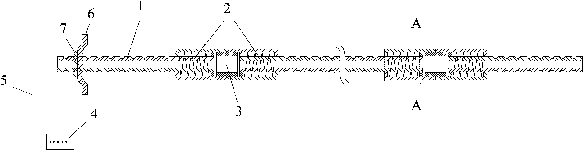
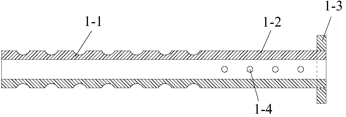
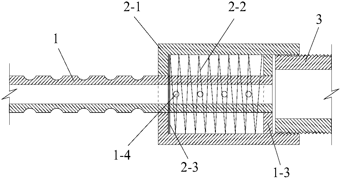
[0023] as attached figure 1 As shown, the full-anchor partition pressure grouting bolt of the present invention is mainly composed of a hollow bolt body 1, a rod body pressure relief device 2, a partition grouting indicator 4, an anchor tray 6 and a lock nut 7; the anchor tray 6 and the lock nut 7 are arranged on the hollow anchor body 1, and the hollow anchor body 1 is cut into 0.5-1.0m long body, and the hollow connecting bolts are arranged between the long body and the long body. 3 Rod body pressure relief devices 2 connected together; the zone grouting indicator 4 is provided with a plurality of indicator lights consistent with the number of rod body pressure relief devices 2, to reflect the pressure relief conditions at different fractured partitions inside the surrounding rock and the stress on the anchor rod body. Each section long body includes an...


PUM


Abstract

The invention discloses a full-anchor partition pressure transferring grouting anchor rod and an application method thereof. The anchor rod comprises a hollow anchor rod body, an anchor rod tray and a lockset nut. The hollow anchor rod body is cut into long section bodies, and rod body pressure transferring devices which are connected together through hollow connecting bolts, wherein one hollow connecting bolt is arranged between every two adjacent long section bodies. Each rod body pressure transferring device comprises a sleeve, wherein a pressure transferring grouting pipe section is sleeved with the sleeve, a flat type pressure sensor and a compression spring abutting against a blocking nut are arranged inside the sleeve in sequence, and all flat type pressure sensors are connected with a partition grouting indicator through wires. According to the full-anchor partition pressure transferring grouting anchor rod, automatic multi-point pressure transferring can be carried out on a plurality of fracture partitions of a deep surrounding rock, the non-coordination deformation breakdown pressure inside the surrounding rock can be effectively released, the anchor rod body can be prevented from being pulled broken and being out of operation, the optimal grouting time points of surrounding rock fracture partitions can be accurately grasped, independent grouting reinforcement is carried out on all fracture partitions timely in a targeted mode, and the stability of the deep roadway partition fracture surrounding rock is effectively improved.

Description

technical field [0001] The present invention relates to a full-anchor partition pressure grouting bolt and its use method, in particular to a full-anchor partition suitable for the reinforcement of deep roadway partitions and cracked surrounding rocks for rock and soil engineering anchoring support such as mine shafts and tunnels. Pressure grouting anchor rod and its usage method. Background technique [0002] With the increase of large-scale mining and mining depth, compared with shallow shaft engineering, deep engineering rock mass is in "three highs and one disturbance" (that is, high ground stress, high ground temperature, high karst water pressure and strong mining disturbance ) in a complex geomechanical environment. When a roadway is excavated in the deep rock mass, there will often be a unique phenomenon of several alternately distributed fracture zones in the surrounding rock of the roadway, that is, the phenomenon of zonal cracking, which leads to a significant di...

Claims


Application Information

Patent Timeline
Patent Type & Authority Applications(China)
IPC IPC(8): E21D21/00E21D20/02
Inventor 陆银龙王连国张继华
Owner CHINA UNIV OF MINING & TECH
Why Eureka
Try Eureka