

Movable testing frame structure
A technology of activity detection and frame structure, which is applied in the direction of measuring devices, measuring instrument components, instruments, etc., can solve the problems affecting the placement of workpieces, and achieve the effect of convenient placement
Inactive Publication Date: 2014-03-19
MT PRECISION MACHINERY MFG
View PDF0 Cites 0 Cited by
- Summary
- Abstract
- Description
- Claims
- Application Information
AI Technical Summary
Problems solved by technology
[0002] When inspecting workpieces, a detection frame is usually set on the bottom plate, and detection tools are set on the detection frame to detect the workpiece. The existing detection frame is a fixed bracket. When large parts or parts are irregular, the bracket May affect workpiece placement
Method used
View moreImage
Smart ImageViewing Examples

Examples
Embodiment Construction
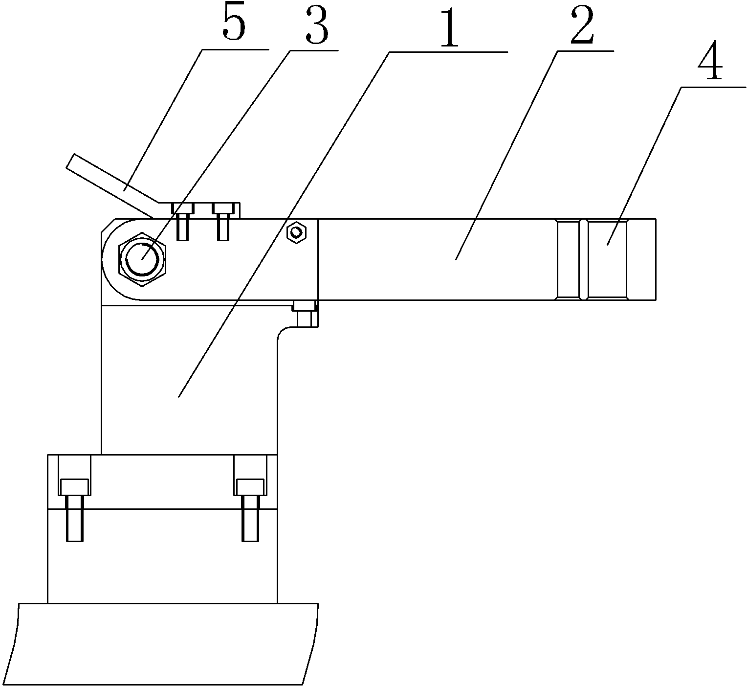
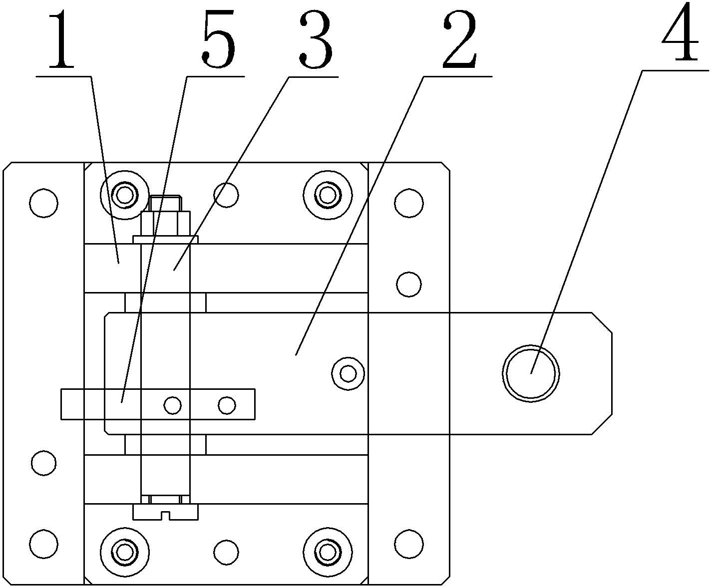
[0009] See figure 1 , figure 2 , a movable detection frame structure, which includes a bracket 1, a flap 2 is arranged on the bracket 1, the flap 2 is connected to the bracket 1 through a pin shaft 3, a detection hole 4 is arranged on the flap 2, and a detection hole 4 is arranged on the flap 2 Tool (not shown in the figure), the limit block 5 is set on the flap 2, since the flap can be rotated through the pin shaft, the flip of the flap can effectively avoid the influence of the detection frame on the placement of the workpiece, and facilitate the convenient placement of the workpiece .
Login to View More PUM
 Abstract
The invention provides a movable testing frame structure which effectively avoids effects exerted by a testing frame to a workpiece and facilitates convenient arrangement of the workpiece. The movable testing frame structure is characterized by comprising a support. The support is provided with a turnover plate; the turnover plate is connected with the support through a pin shaft; and the turnover plate is provided with a detection hole.
Description
technical field [0001] The invention relates to the technical field of product testing fixtures, in particular to a movable testing frame structure. Background technique [0002] When inspecting workpieces, a detection frame is usually set on the bottom plate, and detection tools are set on the detection frame to detect the workpiece. The existing detection frame is a fixed bracket. When large parts or parts are irregular, the bracket May affect the placement of the workpiece. Contents of the invention [0003] In order to solve the above problems, the present invention provides a movable detection frame structure, which effectively avoids the influence of the detection frame on the placement of workpieces, and facilitates the convenient placement of workpieces. [0004] Its technical solution is as follows: an activity detection frame structure, which is characterized in that it includes a bracket, and a flap is arranged on the bracket, and the flap is connected to the b...
Claims
Login to View More Application Information
Patent Timeline
 Patent Type & AuthorityApplications(China)
IPC IPC(8): G01D11/30
Inventor蒋新芬
OwnerMT PRECISION MACHINERY MFG