
A multi-mode signal generating device and signal generating method thereof

A signal generating device, radio frequency signal technology, applied in the direction of electric pulse generator circuit, etc., can solve the problems of multi-mode signal source cannot be included, multi-system simulator wastes resources, slow switching speed, etc., to reduce the risk of test errors, The effect of improving execution speed and improving stability

Active Publication Date: 2017-03-22
CHINA ELECTRONIS TECH INSTR CO LTD
View PDF5 Cites 0 Cited by
  • Summary
  • Abstract
  • Description
  • Claims
  • Application Information

AI Technical Summary

Problems solved by technology

[0003] Traditional multi-mode signal sources usually use multi-radio frequency hardware, and multi-system simulators are a waste of resources, and the switching speed is slow due to complex switching
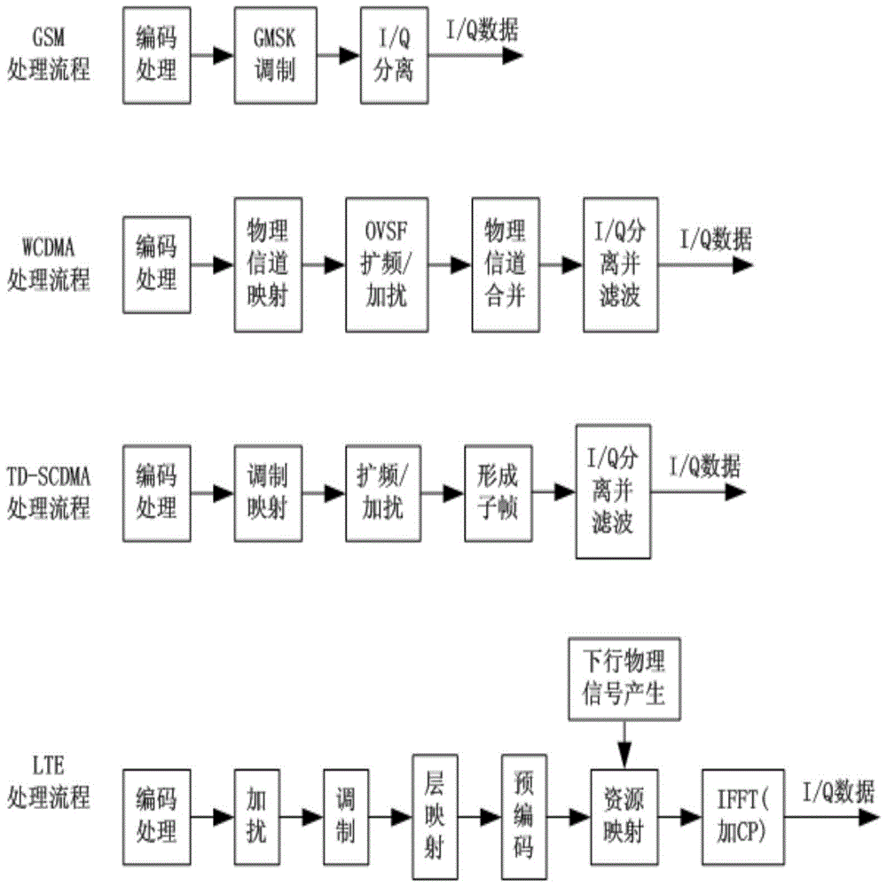
In addition, there is often a problem that a multi-mode signal source cannot cover GSM, WCDMA, TD_SCDMA, and TD_LTE standards, so it is imminent to develop a signal source that includes the above four standards

Method used


Image

  • A multi-mode signal generating device and signal generating method thereof
  • A multi-mode signal generating device and signal generating method thereof
  • A multi-mode signal generating device and signal generating method thereof

Examples


Embodiment Construction

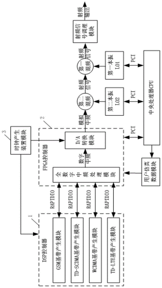
[0023] A kind of multi-mode signal generator, comprises DSP controller 1, and its input and output end is connected with the input and output end of FPGA controller 2, and the output end of FPGA controller 2, the second local oscillator unit LO2 is all connected with the second frequency mixing unit The input end of the second frequency mixing unit and the output end of the first local oscillator unit LO1 are connected to the input end of the first frequency mixing unit, and the output end of the first frequency mixing unit is connected to the input end of the radio frequency signal conditioning module. The output end of the radio frequency signal conditioning module is used as the device output end, and the input and output ends of the central processing unit CPU are respectively connected with the input and output ends of the FPGA controller 2, the second local oscillator unit LO2, and the first local oscillator unit LO1, and the clock generation device module The output term...


PUM


Abstract

The invention relates to a multimode signal generating device, comprising a digital signal processor (DSP) controller, a field programmable gate array (FPGA) controller and a second mixing unit, wherein the input and output ends of the DSP controller are connected with the input and output ends of the FPGA controller; the output ends of the FPGA controller and a second local oscillator unit (LO2) are connected with the input end of the second mixing unit; the output ends of the second mixing unit and the first local oscillator unit (LO1) are connected with the input end of the first mixing unit; the output end of the first mixing unit is connected with the input end of a radio frequency signal conditioning module; the output end of the radio frequency signal conditioning module is used as the output end of the device; the input and output ends of a central processor CPU are respectively connected with the input and output ends of the FPGA controller, the second local oscillator unit (LO2) and the first local oscillator unit (LO1). The invention also discloses a signal generating method of the multimode signal generating device. By adopting the multimode signal generating device and the signal generating method, rapid dynamic scheduling of different modes is achieved, the execution speed of the system is improved, the risk of a test error is reduced, and the stability of a multimode signal source is improved.

Description

technical field [0001] The invention relates to the calibration of GSM, WCDMA, TD_SCDMA and TD_LTE mobile communication terminals and the field of mobile communication teaching, in particular to a multimode signal generating device and a signal generating method thereof. Background technique [0002] With the continuous deepening of LTE industrialization, test equipment, as an important part of the industry chain, has attracted more and more attention from the industry. At present, under the coexistence of LTE, 3G and 2G networks, it is necessary to ensure the compatibility of terminals in various modes of networks. In order to meet the needs of terminal research and development, certification, and production lines, especially in the production line due to the consideration of test costs, it is necessary to support 2G / 3G / 4G multi-mode test instruments at the same time. my country has laid a solid foundation in the research and development of terminal test instruments. Suppo...

Claims


Application Information

Patent Timeline
Patent Type & Authority Patents(China)
IPC IPC(8): H03K3/02
Inventor 王志凌云志黄武王嘉嘉季刚
Owner CHINA ELECTRONIS TECH INSTR CO LTD
Learn More