Optical coupling lens and optical communication module

A technology of optical coupling and optical communication, which is applied in the coupling of optical waveguides and other directions, and can solve the problems of reduced coupling efficiency of optical communication modules

Inactive Publication Date: 2014-03-26
HONG FU JIN PRECISION IND (SHENZHEN) CO LTD +1
View PDF6 Cites 6 Cited by
  • Summary
  • Abstract
  • Description
  • Claims
  • Application Information

AI Technical Summary

Problems solved by technology

[0002] Existing optical communication modules (including light emitting end, optical coupling lens and light receiving end) all adopt passive packaging in technology, because passive packaging cannot directly observe the alignment between the optical coupling lens and the light emitting end or light receiving end through a microscope Due to the situation, there is only a relative position deviation between the light emitting end, the optical coupling lens and the light receiving end after dispensing and curing, and this alignment deviation will reduce the coupling efficiency of the optical communication module

Method used


Image

  • Optical coupling lens and optical communication module
  • Optical coupling lens and optical communication module

Examples


Embodiment Construction

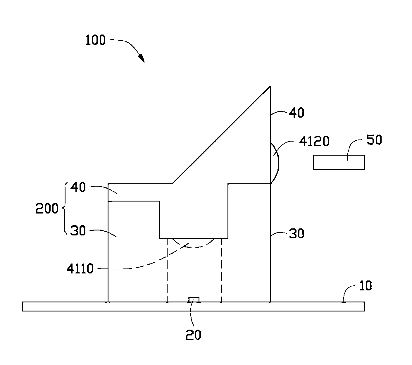
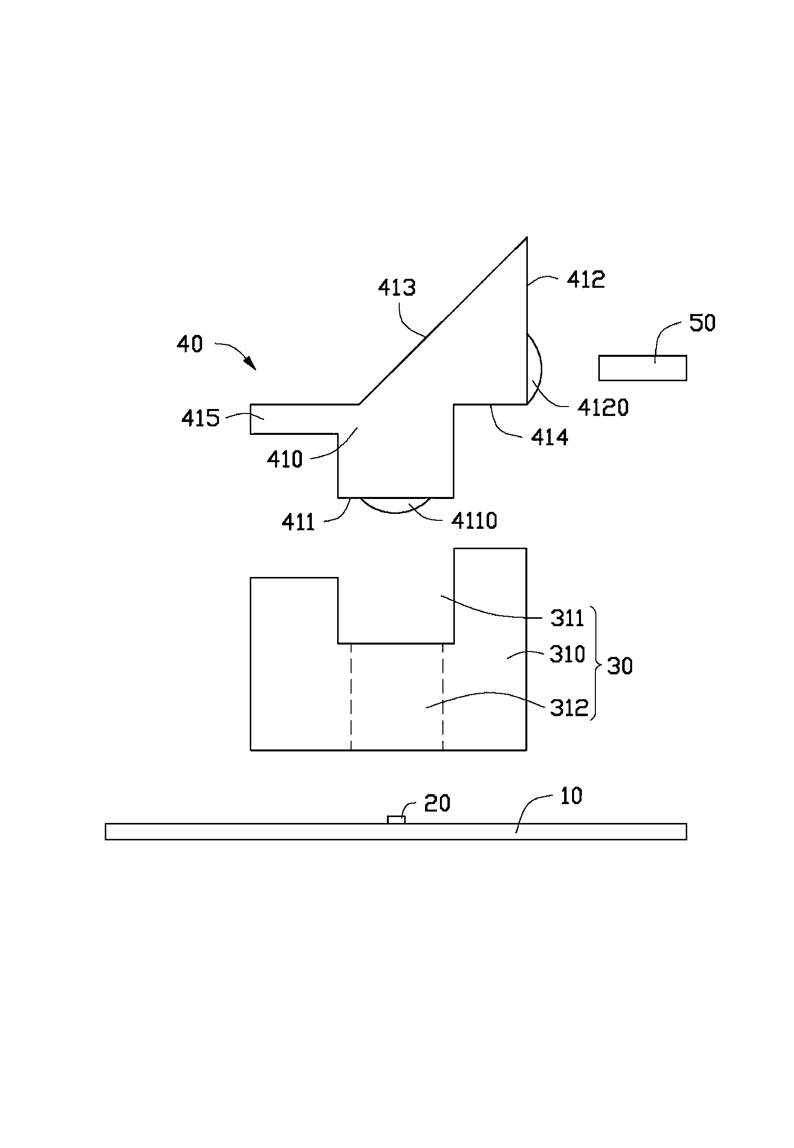
[0012] see figure 1 , figure 2 As shown, the optical communication module 100 provided by the embodiment of the present invention includes a carrier board 10, a light emitting element 20, a fixing device 30, a lens unit 40 and a light receiving element 50, wherein the combination of the fixing device 30 and the lens unit 40 is called an optical coupling lens 200.

[0013] The carrier board 10 is used to carry the light-emitting element 20 , of course, it can also provide electric energy to make the light-emitting element 20 work. The carrier board 10 may be a circuit board, for example, a rigid board or a flexible board. The light-emitting element 20 may be a light-emitting diode, preferably, a surface-type light-emitting diode.

[0014] The fixing device 30 in the optical coupling lens 200 is used to fix the lens unit 40. The fixing device 30 includes a body 310, a groove 311 and a through hole 312 disposed on the body 310, and the through hole 312 is a square hole. The ...


PUM


Abstract

The invention discloses an optical coupling lens which is used for realizing optical signal coupling between a light emitting element and a light receiving element. The optical coupling lens comprises a fixed device and a lens unit, wherein the fixed device is provided with a body; the body is provided with a through hole; the lens unit comprises an incident surface, an emitting surface and a reflecting surface; an included angle of 45 degrees is formed between the reflecting surface and the incident surface; the emitting surface is perpendicular to the incident surface; an optical signal emitted by the light emitting element enters the lens unit through the through hole and the incident surface, and is emitted from the emitting surface after being reflected by the reflecting surface; the light receiving element is used for receiving the optical signal emitted from the emitting surface. The invention further provides an optical communication module with the optical coupling lens.

Description

technical field [0001] The invention relates to an optical coupling lens and an optical communication module. Background technique [0002] Existing optical communication modules (including light emitting end, optical coupling lens and light receiving end) all adopt passive packaging in technology, because passive packaging cannot directly observe the alignment between the optical coupling lens and the light emitting end or light receiving end through a microscope Due to the situation, there is only a relative position deviation between the light emitting end, the optical coupling lens and the light receiving end after dispensing and curing, and this alignment deviation will reduce the coupling efficiency of the optical communication module. Contents of the invention [0003] In view of this, it is necessary to provide an optical coupling lens and an optical communication module with a high optical signal coupling rate. [0004] An optical coupling lens is used to couple ...

Claims


Application Information

Patent Timeline
Patent Type & Authority Applications(China)
IPC IPC(8): G02B6/42
Inventor 洪毅
Owner HONG FU JIN PRECISION IND (SHENZHEN) CO LTD
Why Eureka
Try Eureka