Optical coupling lens and optical communication module

Inactive Publication Date: 2014-07-02
HONG FU JIN PRECISION IND (SHENZHEN) CO LTD +1
View PDF5 Cites 2 Cited by
  • Summary
  • Abstract
  • Description
  • Claims
  • Application Information

AI Technical Summary

Problems solved by technology

[0002] Traditional optical communication modules (including optical transmitter, optical coupling lens, and optical receiving end) all adopt passive packaging in the manufacturing process, because passive packaging cannot directly observe the alignment between the optical coupling lens and the optical transmitting end or optical receiving end through a microscope Due to the situation, there is only a relative position deviation between the light emitting end, the optical coupling lens and the light receiving end after dispensing and curing. This alignment deviation will reduce the coupling efficiency of the optical communication module.

Method used


Image

  • Optical coupling lens and optical communication module
  • Optical coupling lens and optical communication module
  • Optical coupling lens and optical communication module

Examples


Embodiment Construction

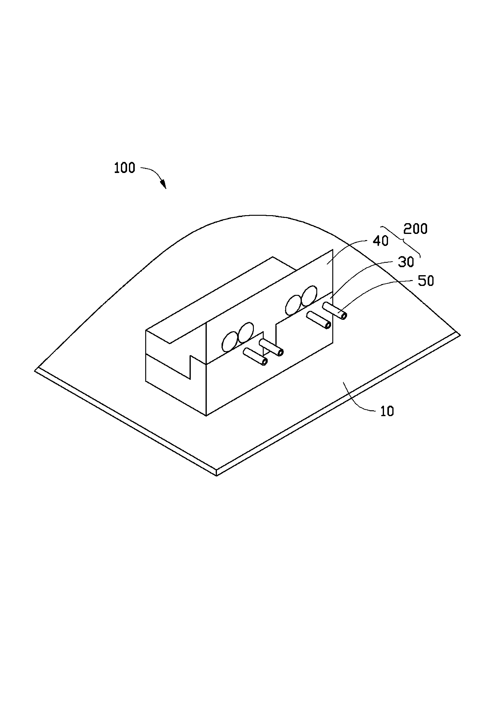
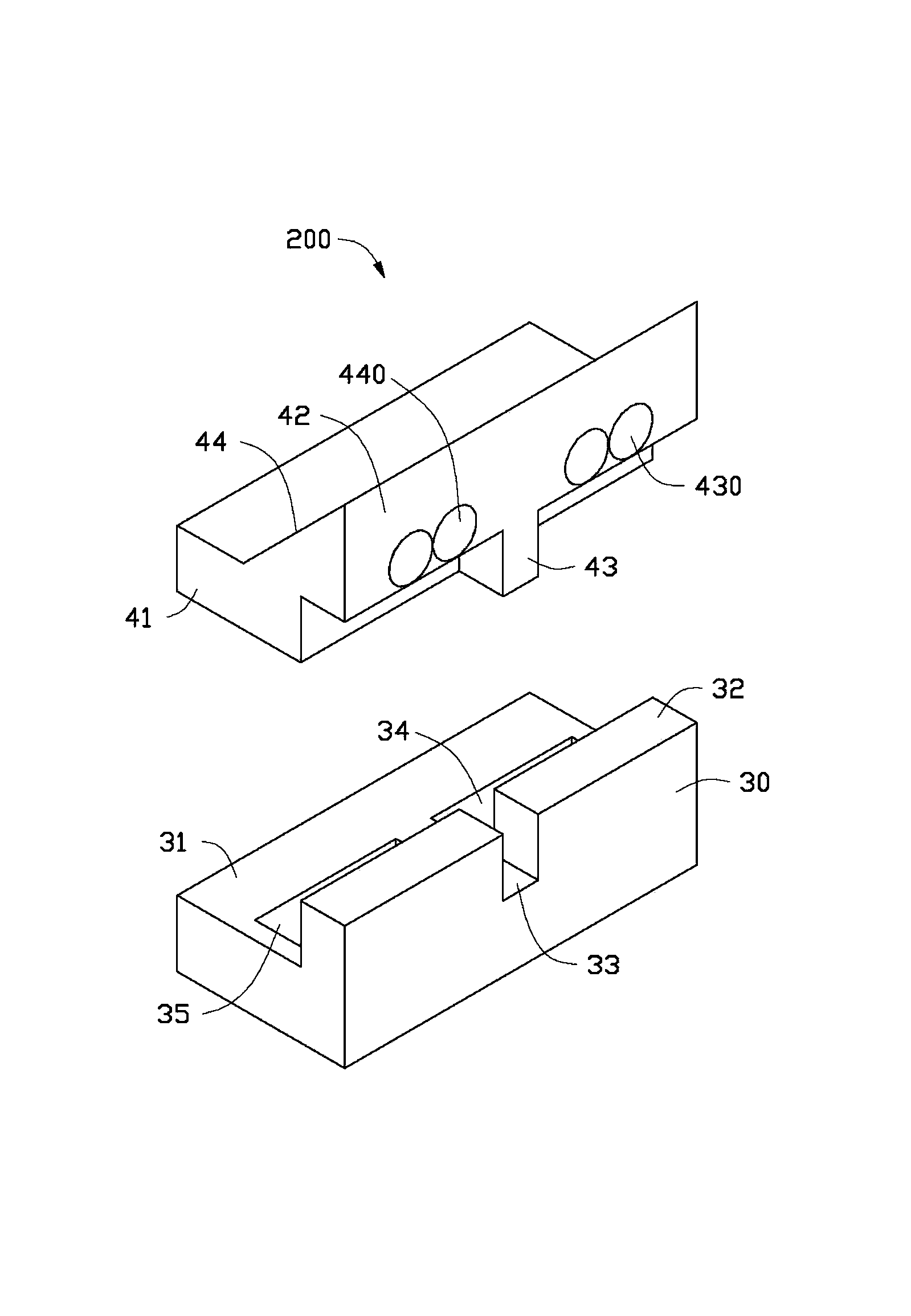
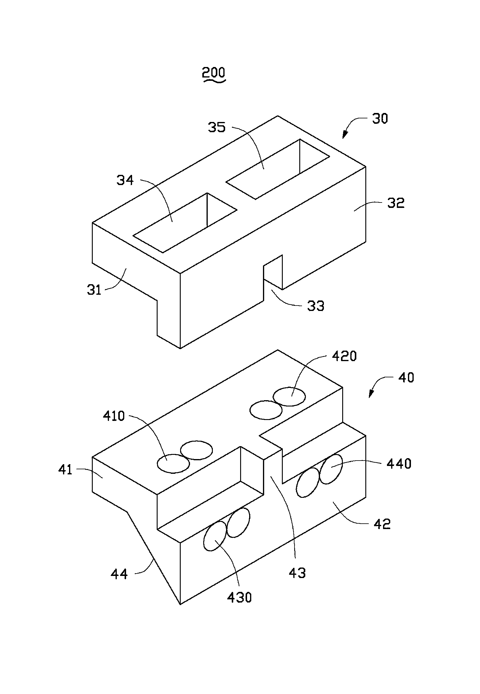
[0014] see figure 1 , figure 2 , image 3 and Figure 4 As shown, the optical communication module 100 provided by the embodiment of the present invention includes a carrier board 10 , a light emitting element 21 , a photodetector 22 , a support unit 30 , a lens unit 40 and an optical fiber 50 .

[0015] Wherein, the light-emitting element 21 and the photodetector 22 are collectively referred to as a photoelectric component, and the combination of the support unit 30 and the lens unit 40 is called an optical coupling lens 200. The support unit 30 is fixed on the carrier plate 10, and the support unit 30 is used to support and fix the lens. The unit 40 aligns the lens unit 40 with the photoelectric unit and the optical fiber 50 to realize optical coupling.

[0016] The carrying board 10 is used to carry the light-emitting element 21 and the photodetector 22 , of course, it can also provide electric energy to make the light-emitting element 21 and the photodetector 22 work. ...


PUM


Abstract

An optical coupling lens is used for enabling an optical signal to be coupled between a photoelectric unit and an optical fiber. The optical coupling lens comprises a support unit and a lens unit. The support unit is used for supporting the lens unit. The support unit is provided with a first clamping portion and a second clamping portion. The second clamping portion is located at one end of the first clamping portion and is vertical to the first clamping portion basically. The second clamping portion is provided with an opening in the middle. The lens unit is provided with a first combination portion and a second combination portion. The second combination portion is provided with a bump corresponding to the opening. The cooperation of the first combination portion and the first clamping portion, the cooperation of the second combination portion and the second clamping portion, as well as the cooperation of the bump and the opening enable the lens unit to be fixed on the support unit. The invention also provides an optical communication module having the optical coupling lens.

Description

technical field [0001] The invention relates to an optical coupling lens and an optical communication module. Background technique [0002] Traditional optical communication modules (including optical transmitter, optical coupling lens, and optical receiving end) all adopt passive packaging in the manufacturing process, because passive packaging cannot directly observe the alignment between the optical coupling lens and the optical transmitting end or optical receiving end through a microscope Due to the situation, there is only a relative position deviation between the light emitting end, the optical coupling lens, and the light receiving end after dispensing and curing, and this alignment deviation will reduce the coupling efficiency of the optical communication module. Contents of the invention [0003] In view of this, it is necessary to provide an optical coupling lens and an optical communication module with a high optical signal coupling rate. [0004] An optical c...

Claims


Application Information

Patent Timeline
Patent Type & Authority Applications(China)
IPC IPC(8): G02B6/42
Inventor 洪毅
Owner HONG FU JIN PRECISION IND (SHENZHEN) CO LTD
Why Eureka
Try Eureka