
Keyboard with trackpad keys

A touchpad and keyboard technology, applied in the input/output process of data processing, input/output of user/computer interaction, instruments, etc., can solve problems such as falsely triggering key signals, moving cursors, occupying space, etc., and achieve reduction false touch effect

Inactive Publication Date: 2016-08-03
ELAN MICROELECTRONICS CORPORATION
View PDF11 Cites 0 Cited by
  • Summary
  • Abstract
  • Description
  • Claims
  • Application Information

AI Technical Summary

Problems solved by technology

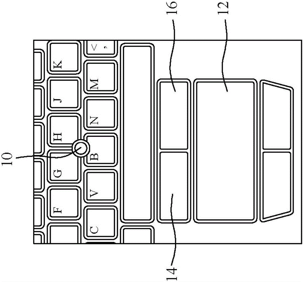
Some notebook computers only use the pointing stick 10 instead of the touchpad 12 in order to reduce the size of the keyboard as much as possible, but the operation of the pointing stick 10 is not as convenient as the touchpad 12
Although using a touchpad or pointing stick is beneficial for users to work for a long time, the hardware cost is high and additional space is required
[0003] U.S. Patent No. 5,841,423 digs long grooves on the blank keys of the keyboard and embeds cylindrical rod sensors to detect sliding, turning or pressing to control the cursor on the screen. Although it can reduce space, the structure is very complicated and easy. Cursor moved due to false sensor touch
U.S. Patent No. 7,659,887 incorporates a miniature touchpad that provides mouse functions on the top surface of the buttons. Although it can also reduce space, it is also easy to cause false triggering of the button signal when operating the mouse function, or move the cursor when the button is pressed.
[0004] The current method of combining touchpad with buttons is to output the information detected by each axis on the touchpad to other control units one by one. Therefore, it is necessary to set up multiple transmission lines around the control unit and the buttons to affect the relationship between the Room space design needs to be improved

Method used


Image

  • Keyboard with trackpad keys
  • Keyboard with trackpad keys
  • Keyboard with trackpad keys

Examples


Embodiment Construction

[0071] In order to make the invention purpose, technical means and technical effect of the present invention more completely and clearly disclosed, the following detailed description is given, and please refer to the accompanying drawings and component numbers.

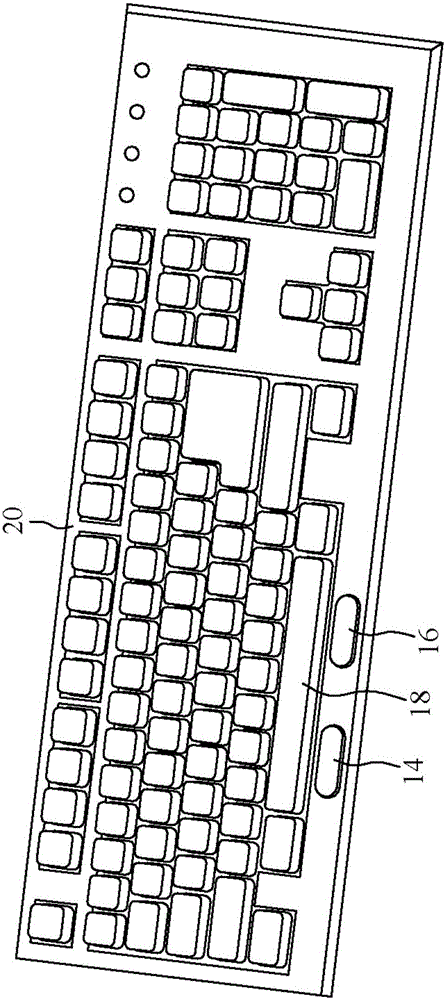
[0072] like figure 2 As shown, the present invention replaces the blank keys of the conventional keyboard 20 with the blank keys 18 of the touchpad, and does not need to occupy additional space. The touchpad blank key 18 not only provides the function of the blank key, but also provides the function of pointing. The left button 14 and the right button 16 of the mouse function are arranged on the lower side of the blank key 18 of the touchpad. The appearance of the touchpad blank key 18 is the same as that of the conventional blank key, but a touchpad (not shown in the figure) is built in, and the touchpad can be operated by touching the surface of the touchpad blank key 18 . In other embodiments, the touchpad can a...


PUM


Abstract

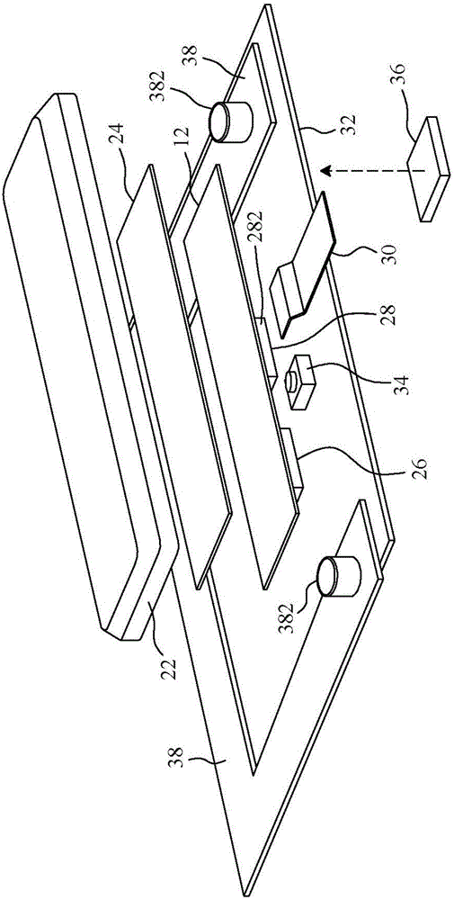
The invention relates to a keyboard with touchpad buttons. The keyboard with the touchpad buttons comprises a keyboard shelf, a mainboard and a plurality of keys. The mainboard and the plurality of keys are disposed on the keyboard shelf. The keys are opposite to a plurality of switches on the surface of the mainboard. On the basis, the touchboard and the keys of a conventional keyboard are combined together in a mechanical structure. The above at least one key comprises a key body disposed on the keyboard shelf, the touchpad adjacent to the key body and a touch chip which is electrically connected with the touchpad and the mainboard and is used for monitoring operations of the touchpad and outputting position information to the mainboard. The operations of the touchpad are still controlled by an independent touch chip but not a controller chip of the keyboard, so as to prevent response sensitivity of the keyboard from reducing. The touchpad is used for providing an orientation function, so that a hand of a user can operate a mouse without leaving the keyboard.

Description

technical field [0001] The present invention relates to a keyboard, in particular to a keyboard with touchpad keys. Background technique [0002] Because of space constraints, laptops are usually equipped with smaller keyboards, and some laptops use a trackpad or a trackpoint to implement mouse functions in order to provide more convenient operations. figure 1 It is a schematic diagram of a notebook computer equipped with a pointing stick 10 and a touchpad 12 at the same time. Usually, the position of the pointing stick 10 is arranged in the gap between the keys of the keyboard, and the position of the touchpad 12 is arranged on the lower side of the key area of ​​the keyboard. The left button 14 and the right button 16 for configuring the mouse function are adjacent to the touchpad 12 . In order to minimize the size of the keyboard, some notebook computers only use the pointing stick 10 instead of the touchpad 12 , but the operation of the pointing stick 10 is not as conve...

Claims


Application Information

Patent Timeline
Patent Type & Authority Patents(China)
IPC IPC(8): G06F3/02G06F3/041
Inventor 徐大凡麦威国钟炳荣钟国盟
Owner ELAN MICROELECTRONICS CORPORATION
Learn More