Telescopic USB (universal serial bus) connection device and telescopic connection device
A connection device and electrical connection technology, which is applied to the parts of the connection device, flexible/rotatable wire connectors, connections, etc., can solve the problems of inconvenient use and limited use, and achieve the effect of convenient use and wide application
- Summary
- Abstract
- Description
- Claims
- Application Information
AI Technical Summary
Problems solved by technology
Method used
Image

Examples
no. 1 example 〕
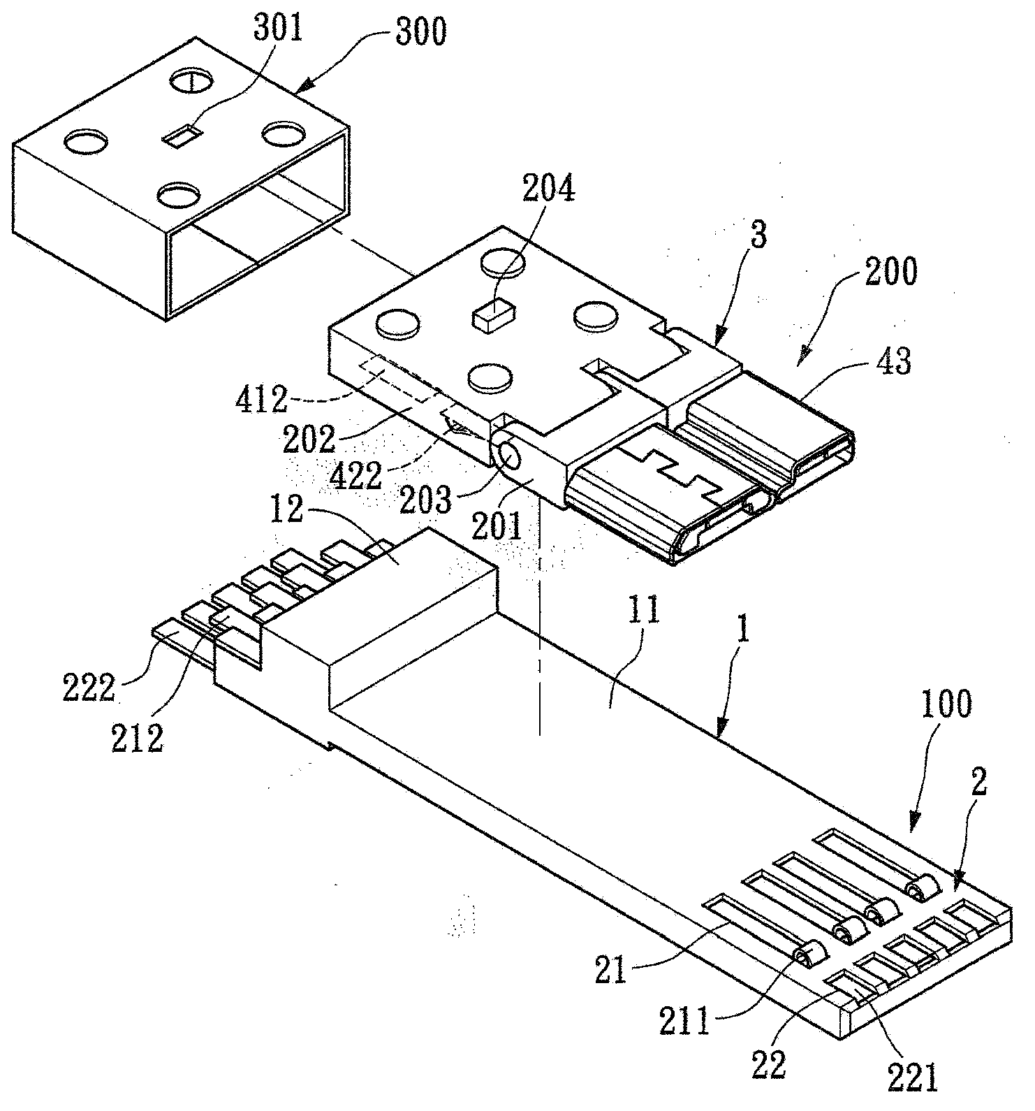
[0086] see Figure 1 to Figure 4 , the present invention provides a scalable and variable USB connection device, including a first module 100 and a second module 200. In this embodiment, the first module 100 is a USB3.0A type (socket) specification, and the second module 2 is the specification of Micro USB (USB3.0 micro-B) (plug), but the specifications of the first module 100 and the second module 200 are not limited, they can be USB A type, USB B type, Micro USB or Mini USB 3.0 Or 2.0USB specifications. The first module 100 and the second module 200 can be plug or socket types.
[0087] The first module 100 includes a first insulating body 1 and a first terminal group 2 , and the first terminal group 2 is disposed on the first insulating body 1 to form the first module 100 together. The first terminal group 2 includes a plurality of terminals 21, 22. In this embodiment, the first terminal group 2 includes a plurality of first terminals 21 and a plurality of second terminal...
no. 2 example
[0100] see Figure 7 The difference between this embodiment and the above-mentioned embodiments is that: the first insulating body 1 and the first terminal group 2 of the first module 100 are covered with a casing 23 . Usually when the second module 200 moves backward to the second position, if a closed casing 23 is provided, the second module 200 will not be able to turn upwards, only when the second module 200 moves forward to the first position, the second module 200 to flip up. In this embodiment, the casing 23 is provided with a sliding slot 231 extending longitudinally. The push button 204 of the second module 200 is movably disposed in the sliding slot 231 , and the sliding slot 231 can be used to guide the second module 200 to move forward and backward.
no. 3 example
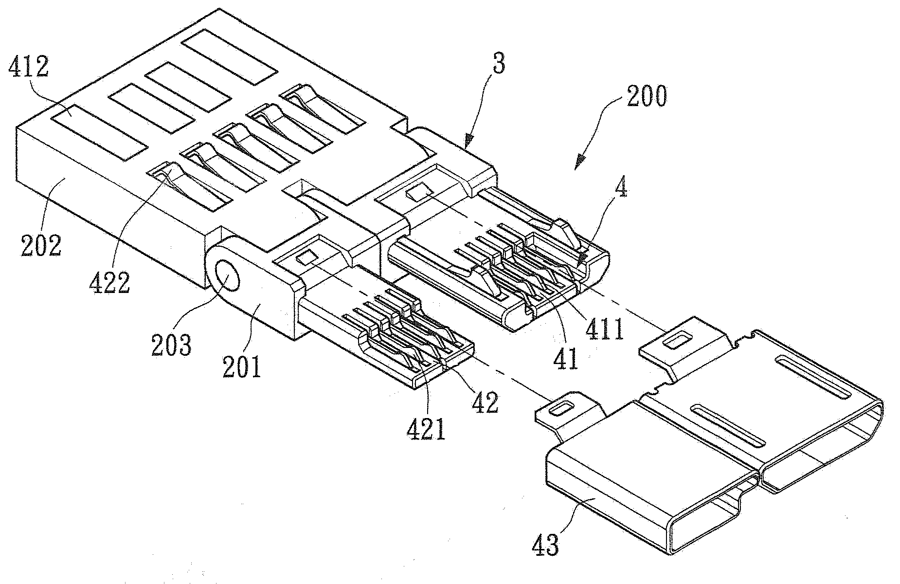
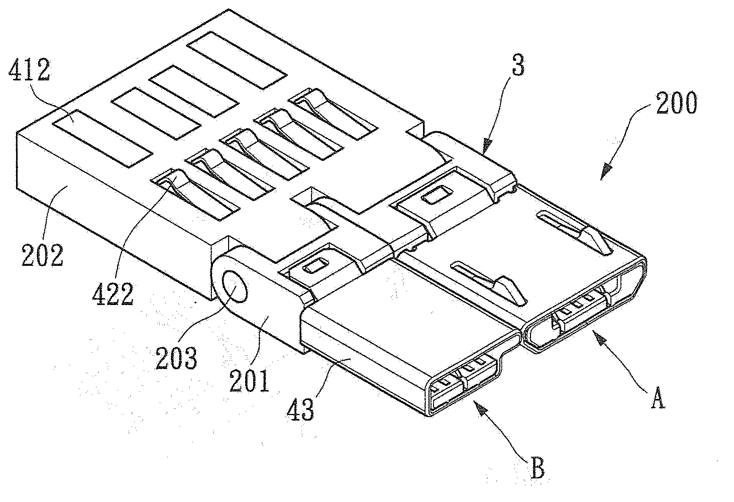
[0102] see Figures 8 to 10 , the difference between this embodiment and the above-mentioned embodiments is that the first terminal group 2 only includes a plurality of first terminals 21, and the second terminal group 4 only includes a plurality of third terminals 41, thereby, the above-mentioned first module 100 can form The second module 200 may be of a MicroUSB (USB 2.0 micro-B) specification or the like. In this embodiment, each of the plurality of first terminals 21 is formed with a first contact portion 211 and a first welding portion 212, and each of the plurality of third terminals 41 is formed with a third contact portion 411 and a first conducting portion. 412. The second module 200 is set on the first module 100 so that it can move forward and backward. When the second module 200 moves to the first position, the plurality of first guiding parts 412 are in contact with the corresponding plurality of first contacts. The portion 211 contacts to electrically connect ...
PUM
 Abstract
Description
Claims
Application Information
 - Generate Ideas
- Intellectual Property
- Life Sciences
- Materials
- Tech Scout
- Unparalleled Data Quality
- Higher Quality Content
- 60% Fewer Hallucinations
Browse by: Latest US Patents, China's latest patents, Technical Efficacy Thesaurus, Application Domain, Technology Topic, Popular Technical Reports.
© 2025 PatSnap. All rights reserved.Legal|Privacy policy|Modern Slavery Act Transparency Statement|Sitemap|About US| Contact US: help@patsnap.com