Stereotactic access devices and methods

a stereotactic access and device technology, applied in the field of stereotactic access devices and methods, can solve the problems of time-consuming, cumbersome frames, time-consuming, etc., and achieve the effect of low additional training and highly versatile application

Active Publication Date: 2013-02-28
VISUALASE
View PDF8 Cites 59 Cited by
  • Summary
  • Abstract
  • Description
  • Claims
  • Application Information

AI Technical Summary

Benefits of technology

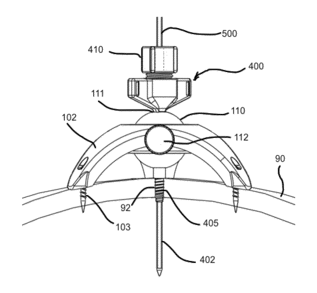
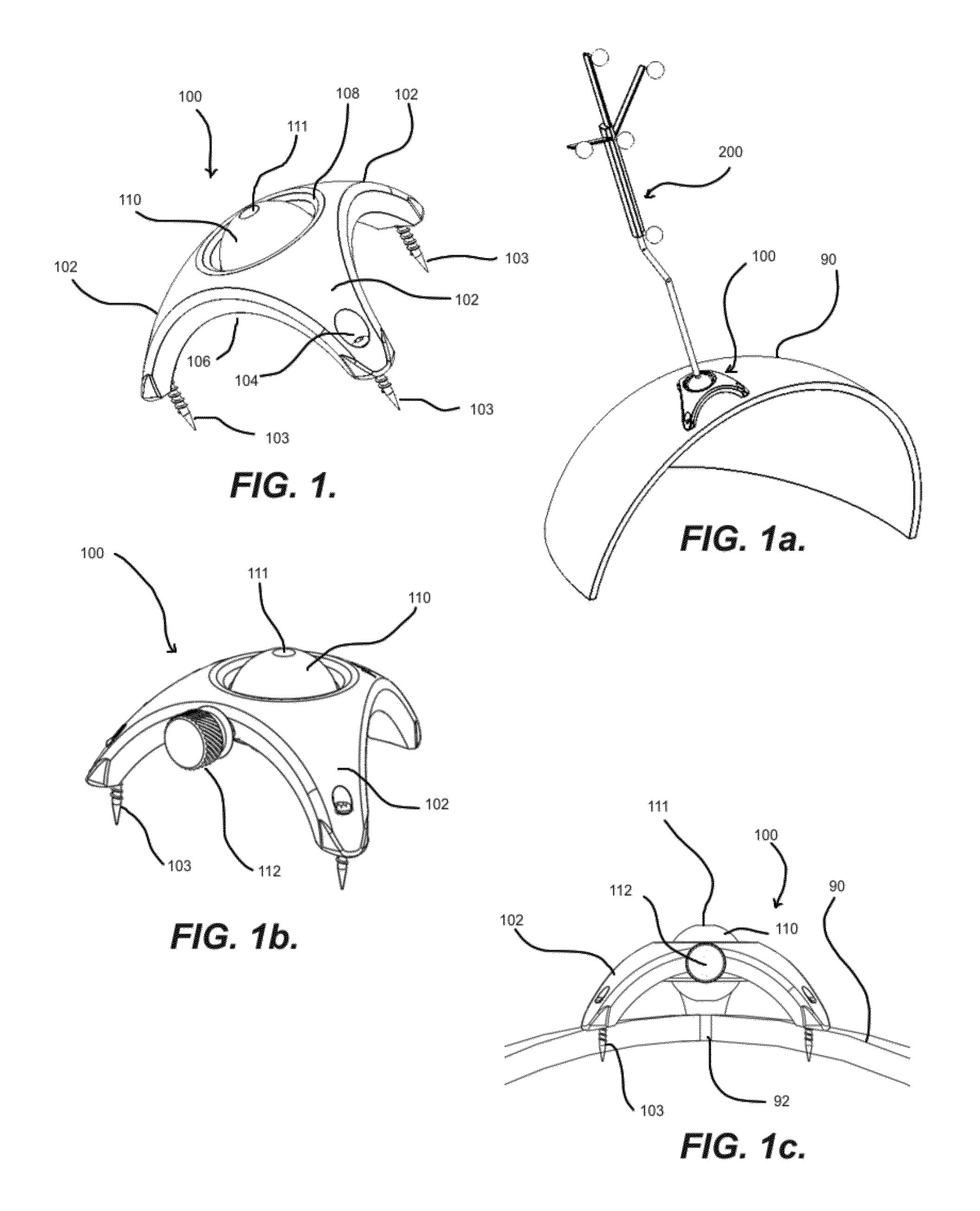
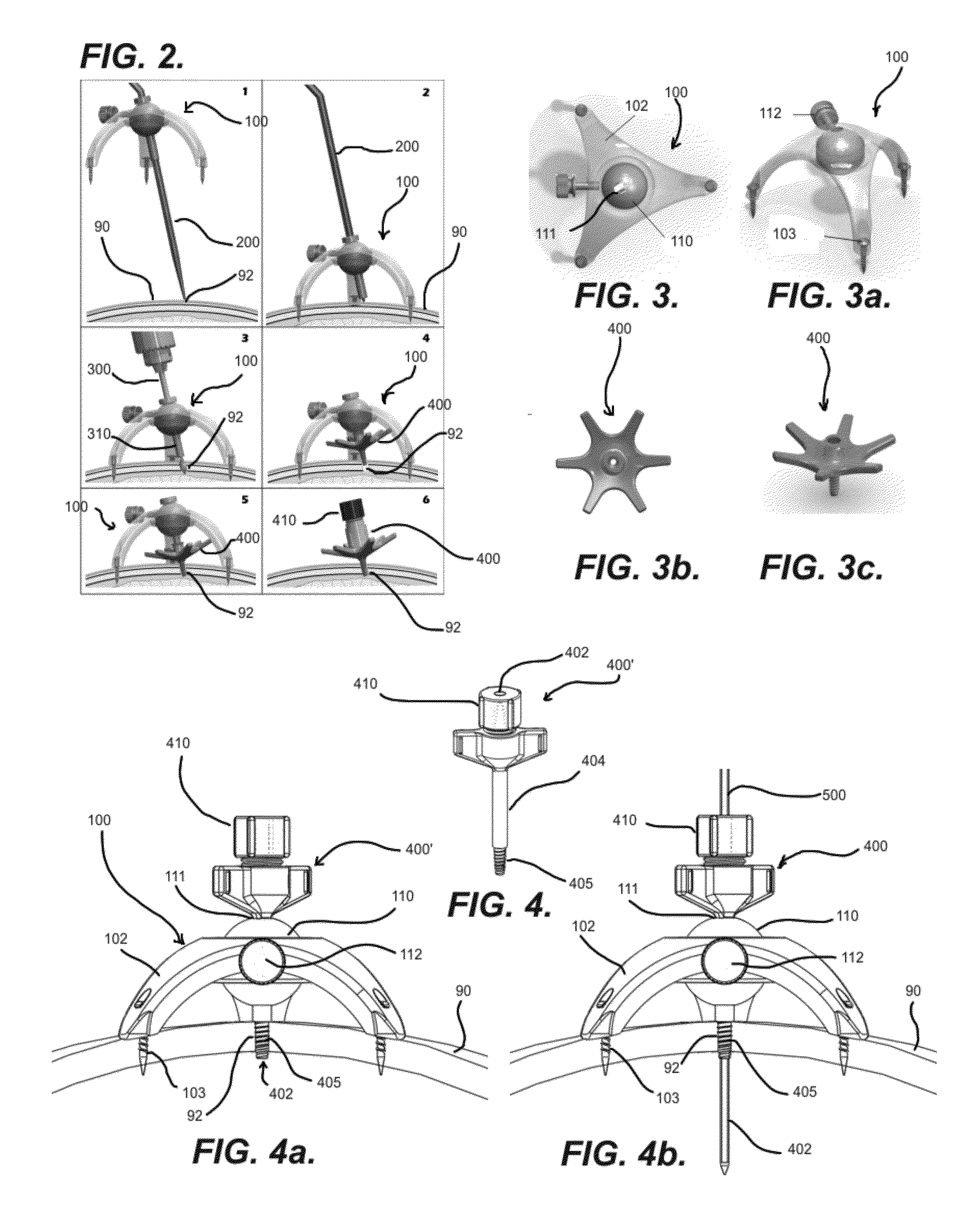
[0018]In some aspects, the stereotactic access device may be desirable as it may generally be utilized with existing and / or standard practice navigation devices, probes and / or systems, and may thus be adaptable to a diverse number of medical practices with very little additional training and / or the need for specialized equipment. For example, the stereotactic access device may generally be compatible and / or be compatible via adapters to receive a standard navigation probe or wand, treatment devices, drills and / or other equipment used in stereotactic surgery. Further, use of the stereotactic access device may generally be intuitive and aid in surgical usage with a minimal number of moving parts and / or components such that, for example, users may use the stereotactic access device with minimal difficulty, while still being highly versatile in application due to a universal use design.

Problems solved by technology

Unfortunately, the frame is cumbersome, uncomfortable for patients, and time intensive.
The drawback to these accessories (Medtronic—Precision Aiming Device and Brainlab Varioguide) are that neither is directly attached to the patient's head, and therefore any movement of the drill is not directly accompanied by a corresponding movement of the head.
Both systems require additional time and resource to set up in the operating room.
Finally, because skin fiducials are movable in relation to the underlying skull, additional error may be realized from the registration alone.

Method used


Image

  • Stereotactic access devices and methods
  • Stereotactic access devices and methods
  • Stereotactic access devices and methods

Examples


Embodiment Construction

[0025]The detailed description set forth below is intended as a description of the presently exemplified devices, methods and materials provided in accordance with aspects of the present invention, and it is not intended to represent the only forms in which the present invention may be practiced or utilized. It is to be understood, however, that the same or equivalent functions and components may be accomplished by different embodiments that are also intended to be encompassed within the spirit and scope of the invention.

[0026]Unless defined otherwise, all technical and scientific terms used herein have the same meaning as commonly understood to one of ordinary skill in the art to which this invention belongs. Although any methods, devices and materials similar or equivalent to those described herein can be used in the practice or testing of the invention, the exemplified methods, devices and materials are now described.

[0027]This invention is directed to devices and methods for ste...


PUM


Abstract

This invention is directed to devices and methods for stereotactic access, and particularly to a frameless stereotactic access device for accessing a body cavity and methods therefor. In general, a stereotactic device may include portions or features for fixing the device to a portion of a patient's body, such as, for example, a skull, such that the device may be generally spatially fixed in relation to the patient's body or part thereof. The stereotactic device may also generally include portions or features for guiding a medical device or other device at a particular trajectory in relation to the patient's body or part thereof.

Description

CROSS-REFERENCE TO RELATED APPLICATIONS[0001]This application claims the priority of U.S. provisional patent application Ser. No. 61 / 525,911, filed Aug. 22, 2011, and entitled “STEREOTACTIC ACCESS DEVICE”, the contents of which are hereby incorporated by reference in its entirety.FIELD OF THE INVENTION[0002]This invention relates to devices and methods for stereotactic access, and particularly to a frameless stereotactic access device for accessing a body cavity and methods therefor.BACKGROUND OF THE INVENTION[0003]Stereotactic head frames have a long and proven history in neurosurgery. The two most commonly used are the Leksell (Elekta) and CRW (Integra Neurosciences) frames. In these procedures, a frame is mounted to the head by screwing pins directly against the patient's skull for fixation at four points. The head with attached frame are then imaged by CT or MRI to identify targets, either manually or more frequently with computerized software, in relation to the external frame....

Claims


Application Information

Patent Timeline
Patent Type & Authority Applications(United States)
IPC IPC(8): A61B19/00
CPCA61B19/201A61B2019/5483A61B2019/208A61B19/203A61B90/11A61B90/14A61B2090/103A61B2090/3983A61B17/00234
Inventor GOWDA, ASHOKMCNICHOLS, ROGERHOUSSIERE, CHARLES
Owner VISUALASE
Why Eureka
Try Eureka