
power tool

A power tool and power source technology, which is applied in the field of power tools, can solve the problems that the ring gear and the meshing gear cannot be smoothly meshed, and cannot be smoothly shifted and switched, so as to achieve the effect of smooth change

Active Publication Date: 2016-01-20
PANASONIC INTELLECTUAL PROPERTY MANAGEMENT CO LTD
View PDF8 Cites 0 Cited by
  • Summary
  • Abstract
  • Description
  • Claims
  • Application Information

AI Technical Summary

Problems solved by technology

In this state, even if the drive motor starts to rotate the transmission mechanism, there is a possibility that the ring gear and the meshing gear may not mesh smoothly.
In other words, there may be cases where smooth shifting cannot be performed.

Method used


Image

  • power tool
  • power tool
  • power tool

Examples


no. 1 approach )

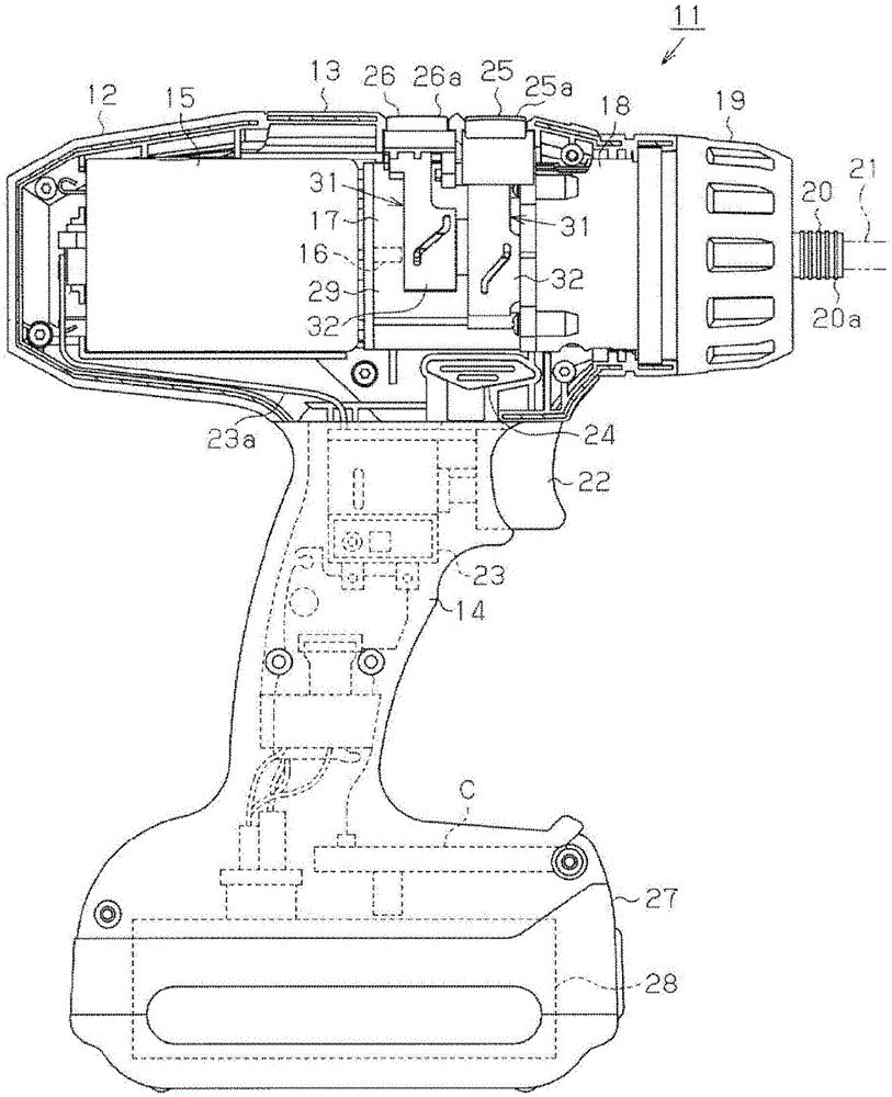
[0034] Below, based on Figure 1 to Figure 12 The first embodiment will be described. figure 1 A power tool 11 as an example of a power tool is schematically shown.

[0035] like figure 1 As shown, the electric power tool 11 of the first embodiment is a hand-held tool that can be held with one hand, and can be used, for example, as an electric drive for concrete. The power tool 11 includes a main body housing 12 as an exterior. The main body casing 12 has a bottomed cylindrical body portion 13 (in the figure 1 Only the left half is shown in the figure) and the handle portion 14 from the body portion 13 to one direction ( figure 1 middle is below) extends out.

[0036] At the base end side of the body portion 13 within the body portion 13 (at the figure 1 The motor 15 is accommodated at a position on the left side). The motor 15 includes an output shaft 16 having an axis of rotation that coincides with the axis of the body portion 13 and is directed toward the front...

no. 2 approach )

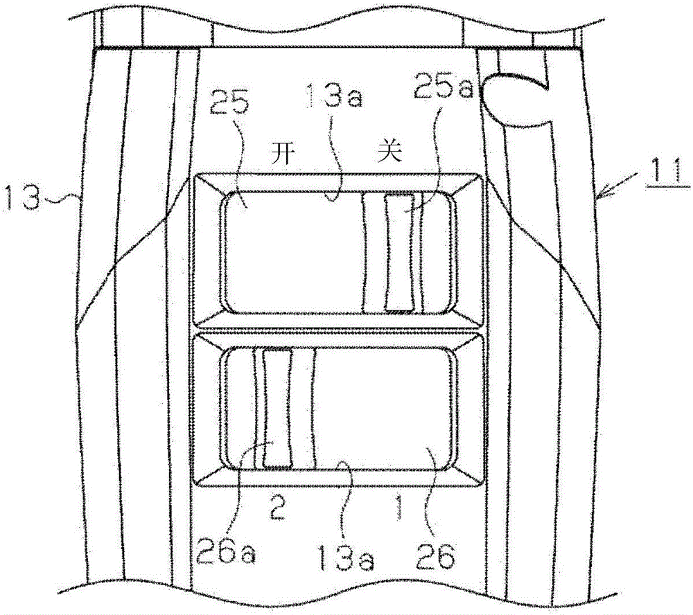
[0087] Next, use Figure 13 to Figure 17 The second embodiment will be described. In this second embodiment, the configuration of the speed change switching mechanism portion 31 of the first embodiment is changed. Hereinafter, the same reference numerals are assigned to the same components as those of the first embodiment, and descriptions thereof will be omitted. In addition, in Figure 13 , Figure 16 as well as Figure 17 In the transmission gear mechanism 30, only the ring gears 42 and 46 that move during shifting are shown, and the other gear groups are omitted.

[0088] like Figure 13 and Figure 14 As shown, the speed change switching mechanism portion 71 of the second embodiment is provided between the respective operation portions 25 and 26 and the speed change mechanism portion 17, and can convert the operation force of the respective operation portions 25 and 26 in the direction around the thrust axis into the thrust axis The force in the axial direction is ...


PUM


Abstract

A power tool (11) includes a transmission mechanism (17) capable of selecting one of a plurality of transmission gear ratios by changing a combination of gears of a gear train (30) to be meshed with each other, a transmission ratio switching operation unit (25; 26) capable of turning around the thrust shaft and operating to change the combination of the gears, a gear operation mechanism (63, 29a, 42c, 46b) to move a transmission gear (42; 46) of the gear train in a thrust shaft direction in accordance with turning motion of the transmission ratio switching operation unit, and a biasing mechanism (32, 65) to bias the gear operation mechanism in accordance with the turning motion of the transmission ratio switching operation unit such that the transmission gear moves in the thrust shaft direction and meshes with a meshed gear corresponding to the selected transmission gear ratio.

Description

technical field [0001] The present invention relates to a power tool including a speed change mechanism part for changing the rotational speed of a drive source and a speed change switching operation part for switching the speed change ratio of the speed change mechanism part. Background technique [0002] An electric power tool, which is an example of a power tool, includes a motor as a drive source, a speed change mechanism portion for changing the rotational speed of the motor, a drive shaft rotatable at a speed change ratio of the speed change mechanism portion, and a speed change ratio for switching the speed change mechanism portion The shift switch operation part of the . Patent Documents 1 to 4 describe examples of such electric tools. For example, in the electric power tool described in Patent Document 1, when the shift paddle (Japanese: 変speed パドル) (shift switching operation part) is rotated in the direction around the thrust axis, the shift switching ring is rota...

Claims


Application Information

Patent Timeline
Patent Type & Authority Patents(China)
IPC IPC(8): B25B21/00B25B23/157
CPCB25F5/001
Inventor 西井和彦山本真佐雄
Owner PANASONIC INTELLECTUAL PROPERTY MANAGEMENT CO LTD
Learn More