
Convenient-to-adjust machining platform

A technology of processing platform and processing table, which is applied in the direction of workbench, metal processing equipment, metal processing machinery parts, etc., can solve the problems of inconvenient operation, high maintenance cost, single structure, etc., and achieves convenient maintenance, compact structure, and favorable The effect of promotion

Active Publication Date: 2020-05-22
苏州都源精密机械有限公司
View PDF4 Cites 0 Cited by
  • Summary
  • Abstract
  • Description
  • Claims
  • Application Information

AI Technical Summary

Problems solved by technology

At present, most of the processing platforms are similar to a table, with a single structure and few functions. In many processing processes, the workpiece needs to be moved at a constant speed, and the operator moves the workpiece manually, which will reduce the processing accuracy and lead to low production efficiency.
[0003] Chinese patent (publication number: CN108000169A) discloses a processing platform adjustment device. The processing platform, adjusting turntable, translation support and fixed base included in the invention are arranged horizontally from top to bottom, and the translation support is slid on the translation guide along the horizontal direction. The adjusting turntable is set horizontally on the upper side of the translation support, and the adjusting sleeve is vertically set between the lower threaded rod and the upper threaded rod. The rotating platform is horizontally connected to the adjusting turntable. Rotate the rack, the two sides of the movable rack are respectively meshed with the adjusting gear and the rotating rack, and the two adjustment guide grooves set horizontally through the processing platform are respectively slidingly provided with adjustment guide plates on both sides, and the upper screw rod is pressed vertically. Sliding is provided with a compression fixing plate, which adjusts the position of the processing platform through the action of gear meshing and screw connection; however, the structure of the device is complicated, the operation is inconvenient, and the maintenance cost is high, so it is not suitable for small and medium-sized workshops

Method used


Image

  • Convenient-to-adjust machining platform
  • Convenient-to-adjust machining platform
  • Convenient-to-adjust machining platform

Examples


Embodiment 1

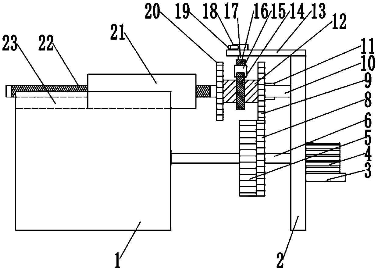
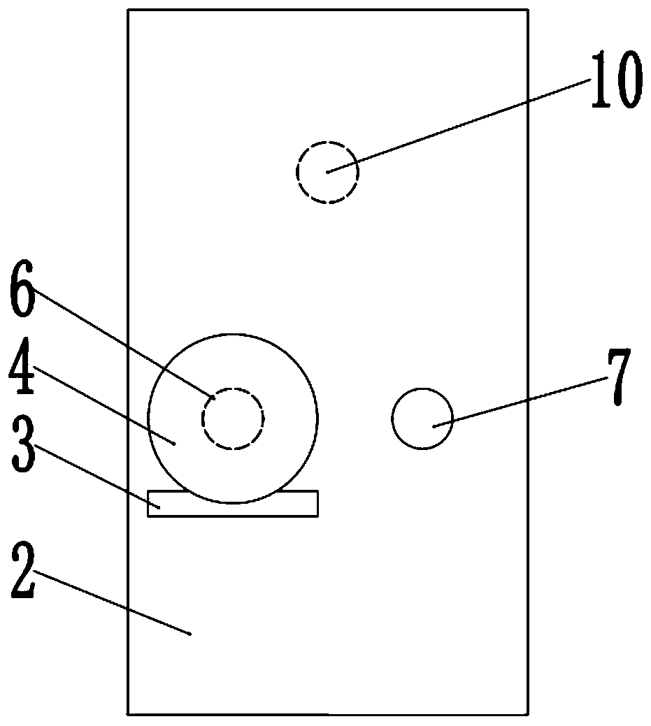
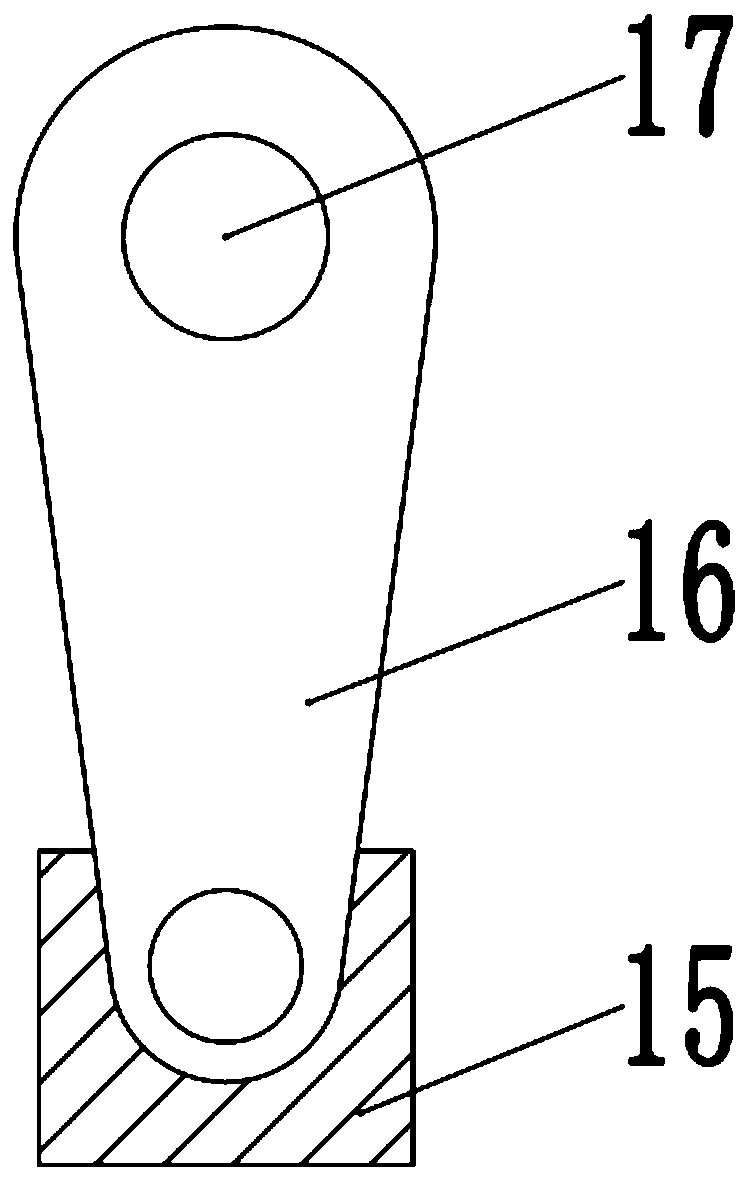
[0027] see Figure 1-3 , a processing platform that is easy to adjust, including a support frame 2, the right side of the support frame 2 is fixedly connected to the motor base 3, the top of the motor base 3 is fixedly connected to the motor 4, the output shaft of the motor 4 is fixedly connected to the first rotating shaft 6, and the left end of the first rotating shaft 6 Rotationally connected to the processing table 1, the top of the processing table 1 is provided with a chute 23, and the chute 23 is slidingly connected to the placement table 21.

[0028] The outside of the first rotating shaft 6 is fixedly connected to the first gear 5, the first gear 5 is meshed with the second gear 8, the second gear 8 is fixedly connected to the second rotating shaft 7, and the second rotating shaft 7 is rotatably connected to the processing table 1 and the support frame The left side of the support frame 2 between the 2 is connected to the third rotating shaft 10, the third rotating sh...

Embodiment 2

[0031] see Figure 4 and 5 , the other content of this embodiment is the same as that of Embodiment 1, the difference is that: the top of the fixed plate 13 is fixedly connected to the fixed rod 24, the surface of the fixed rod 24 is slidably connected to the pin 25, and the tail end of the pin 25 is fixedly connected to the spring 26, The other end of the spring 26 is fixedly connected to the inner wall of the chute 27, the chute 27 is located in the control rod 19, the rotating disk 18 is connected to the fixed rod 24 in rotation, when the position of the workpiece needs to be moved, the control rod 19 is rotated, and the control rod 19 The pin 25 rotates to the corner of the surface of the fixed rod 24, the spring 26 is compressed, and the pin 25 slides in the chute 27. When the pin 25 slides to the plane of the fixed rod 24, the spring 26 recovers, so that the position of the control rod 19 Fixed to prevent it from sliding, the right side of the third rotating shaft 10 is...


PUM


Abstract

The invention relates to the technical field of machining, in particular to a convenient-to-adjust machining platform. The convenient-to-adjust machining platform comprises a supporting frame, whereina third rotating shaft is rotationally connected to the left side of the supporting frame, a sleeve rotationally is connected to the third rotating shaft through a flat key, and a third gear and a fourth gear are fixedly connected to two ends of the outer side of the sleeve; a screw is fixedly connected to the left end of the third rotating shaft; and a fixing plate is fixedly connected to the top of the supporting frame, wherein a connecting rod is rotationally connected into the fixing plate, a rotating arm is fixedly connected to the bottom of the connecting rod, and a clamping seat is rotationally connected to the bottom of the rotating arm and slidably connected with a fixing ring. The convenient-to-adjust machining platform is suitable for machining of small and medium workshops; and a control structure is composed of a rotary disc, the connecting rod, the rotating arm and the clamping seat, so that the meshing conditions of the gears is changed, and a containing table can be driven to horizontally move on a machining table under threaded connection effects of the screw. The convenient-to-adjust machining platform is compact in structure and easy to operate, and the motion state of the containing table can be changed only through rotating a control rod; and the machining platform is low in cost, convenient to repair and maintain, thus being particularly suitable for thesmall and medium workshops and easy to popularize.

Description

technical field [0001] The invention relates to the technical field of mechanical processing, in particular to a processing platform that is easy to adjust. Background technique [0002] In industrial processing, processing platforms are widely used. Basically, each processing post will have a processing platform, and workpieces are processed on different processing platforms. Usually in the individual workshop processing, the measurement, grinding, precision machining of the workpiece all need to use the processing platform. At present, most of the processing platforms are similar to a table, with a single structure and few functions. In many processing processes, the workpiece needs to be moved at a constant speed, and the operator moves the workpiece manually, which will reduce the processing accuracy and lead to low production efficiency. [0003] Chinese patent (publication number: CN108000169A) discloses a processing platform adjustment device. The processing platform...

Claims


Application Information

Patent Timeline
IPC IPC(8): B23Q1/25B25H1/14
CPCB23Q1/25B25H1/14
Inventor 秦继中
Owner 苏州都源精密机械有限公司
Learn More