An easily adjustable processing platform
A technology of processing platform and processing table, which is applied in the direction of workbench, metal processing equipment, metal processing machinery parts, etc., can solve the problems of inconvenient operation, single structure, and reduced processing accuracy, and achieve convenient maintenance, simple operation, and favorable promotion Effect
- Summary
- Abstract
- Description
- Claims
- Application Information
AI Technical Summary
Problems solved by technology
Method used
Image
Examples
Embodiment 1
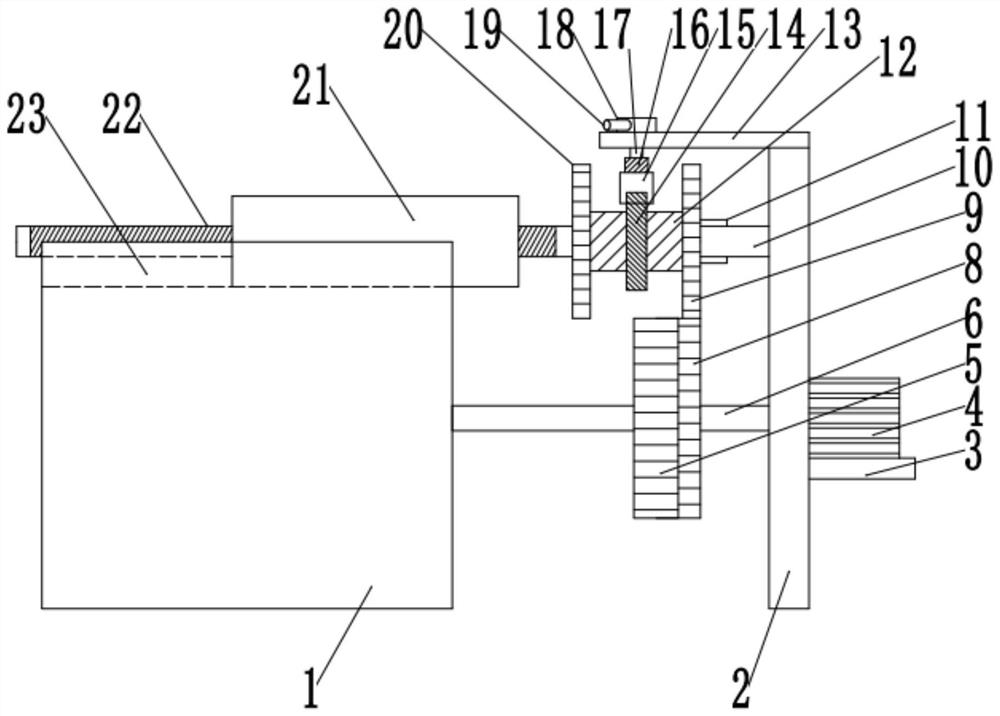
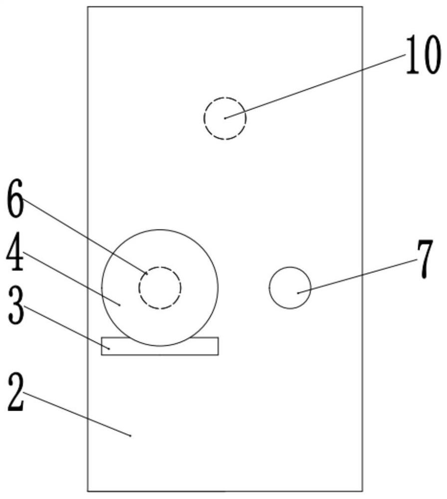
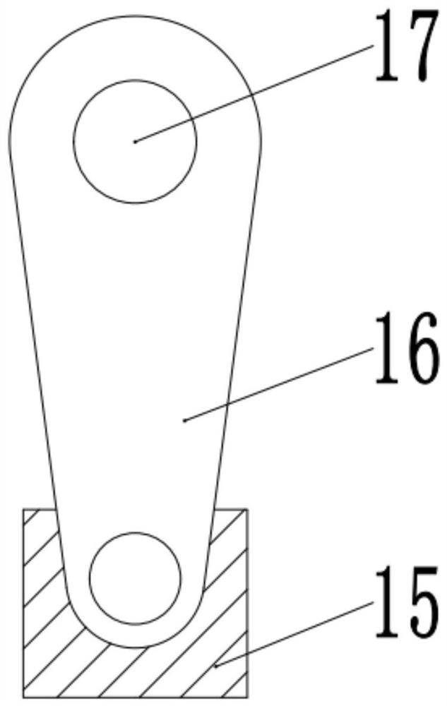
[0027] see Figure 1-3 , a processing platform that is easy to adjust, including a support frame 2, the right side of the support frame 2 is fixedly connected to the motor base 3, the top of the motor base 3 is fixedly connected to the motor 4, the output shaft of the motor 4 is fixedly connected to the first rotating shaft 6, and the left end of the first rotating shaft 6 Rotationally connected to the processing table 1, the top of the processing table 1 is provided with a chute 23, and the chute 23 is slidingly connected to the placement table 21.
[0028] The outside of the first rotating shaft 6 is fixedly connected to the first gear 5, the first gear 5 is meshed with the second gear 8, the second gear 8 is fixedly connected to the second rotating shaft 7, and the second rotating shaft 7 is rotatably connected to the processing table 1 and the support frame The left side of the support frame 2 between the 2 is connected to the third rotating shaft 10, the third rotating sh...
Embodiment 2
[0031] see Figure 4 and 5 , the other content of this embodiment is the same as that of Embodiment 1, the difference is that: the top of the fixed plate 13 is fixedly connected to the fixed rod 24, the surface of the fixed rod 24 is slidably connected to the pin 25, and the tail end of the pin 25 is fixedly connected to the spring 26, The other end of the spring 26 is fixedly connected to the inner wall of the guide groove 27, and the guide groove 27 is located in the control rod 19. The rotating disk 18 is connected to the fixed rod 24 in rotation. The pin 25 rotates to the corner of the surface of the fixed rod 24, the spring 26 is compressed, and the pin 25 slides in the guide groove 27. When the pin 25 slides to the plane of the fixed rod 24, the spring 26 recovers, so that the position of the control rod 19 is fixed. , to prevent it from sliding, the right side of the third rotating shaft 10 is fixedly connected to the crank handle 28, when the motor 4 breaks down and c...
PUM
 Abstract
Description
Claims
Application Information
 - R&D
- Intellectual Property
- Life Sciences
- Materials
- Tech Scout
- Unparalleled Data Quality
- Higher Quality Content
- 60% Fewer Hallucinations
Browse by: Latest US Patents, China's latest patents, Technical Efficacy Thesaurus, Application Domain, Technology Topic, Popular Technical Reports.
© 2025 PatSnap. All rights reserved.Legal|Privacy policy|Modern Slavery Act Transparency Statement|Sitemap|About US| Contact US: help@patsnap.com


