
Anti-siphon structure for water inlet valve

An anti-siphon and water inlet valve technology, which is applied to flushing equipment with water tanks, water supply devices, buildings, etc., can solve problems such as large errors in water inlet valves, CL line label errors, and polluted water sources

Active Publication Date: 2014-04-02
LAB XIAMEN SANITARY FITTINGS
View PDF4 Cites 5 Cited by
  • Summary
  • Abstract
  • Description
  • Claims
  • Application Information

AI Technical Summary

Problems solved by technology

[0004] When the water is suddenly cut off, a large negative pressure is formed in the inner core tube, and the water inlet of the inner core tube is blocked and closed by the water stop mechanism. The water outlet channel is cut off to play an anti-siphon effect, however, its anti-siphon effect is still not ideal
[0005] At the same time, when the water inlet valve needs to be marked with the CL line (anti-siphon line) when it leaves the factory, it is usually necessary to conduct a destructive test on the gasket of the water inlet valve, such as placing a steel wire between the gasket and the fitting surface, so as to determine the test. The position of the CL line is marked on the body of the water inlet valve, but the size and shape of the steel wire between the gasket and the fitting surface are different, which easily causes a large error in the labeling of the CL line, which in turn causes a large error in the installation of the water inlet valve. It is easy to produce siphon phenomenon and pollute the water source

Method used


Image

  • Anti-siphon structure for water inlet valve
  • Anti-siphon structure for water inlet valve
  • Anti-siphon structure for water inlet valve

Examples


Embodiment Construction

[0046] The present invention will be described in detail below in conjunction with the accompanying drawings and specific embodiments.

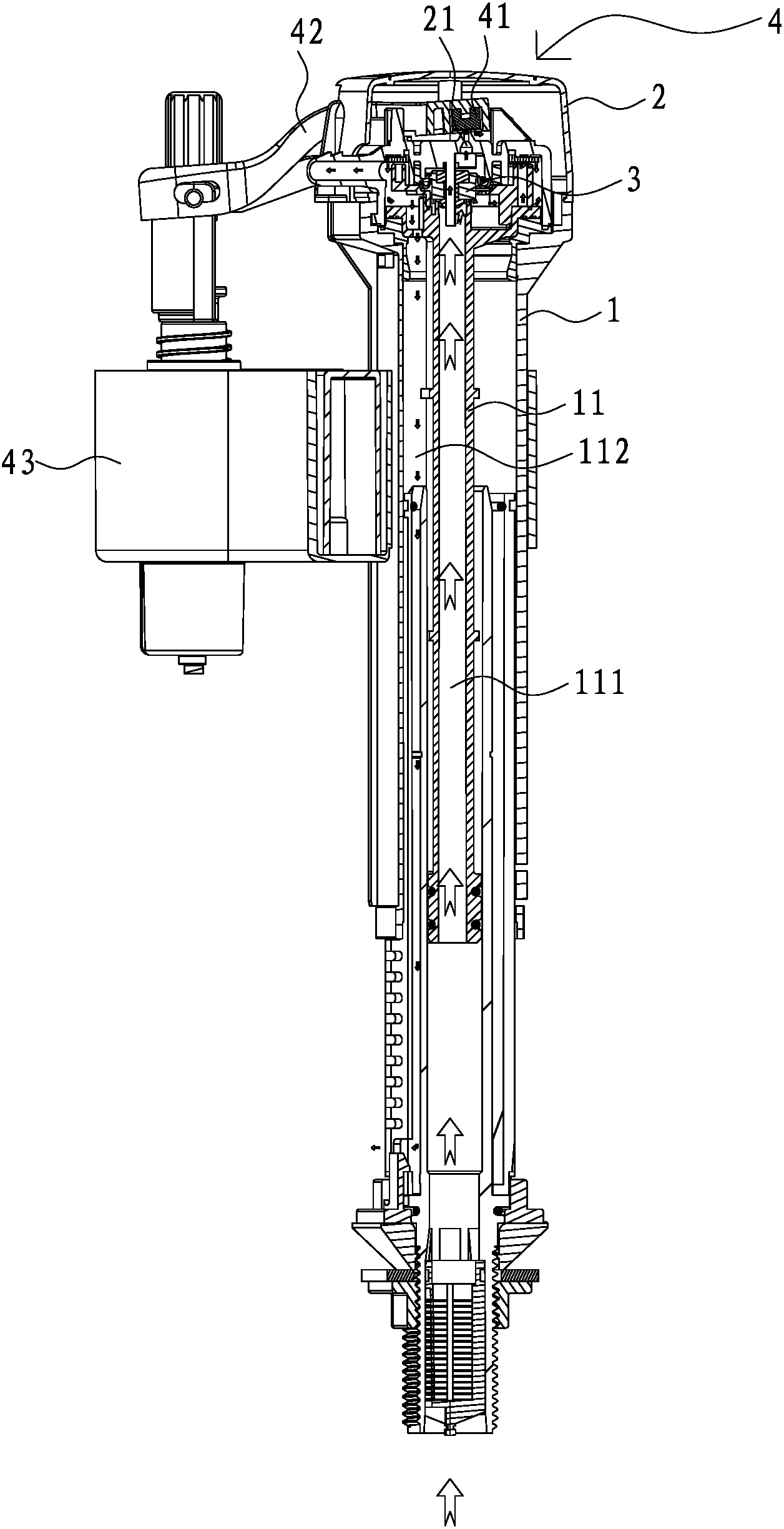
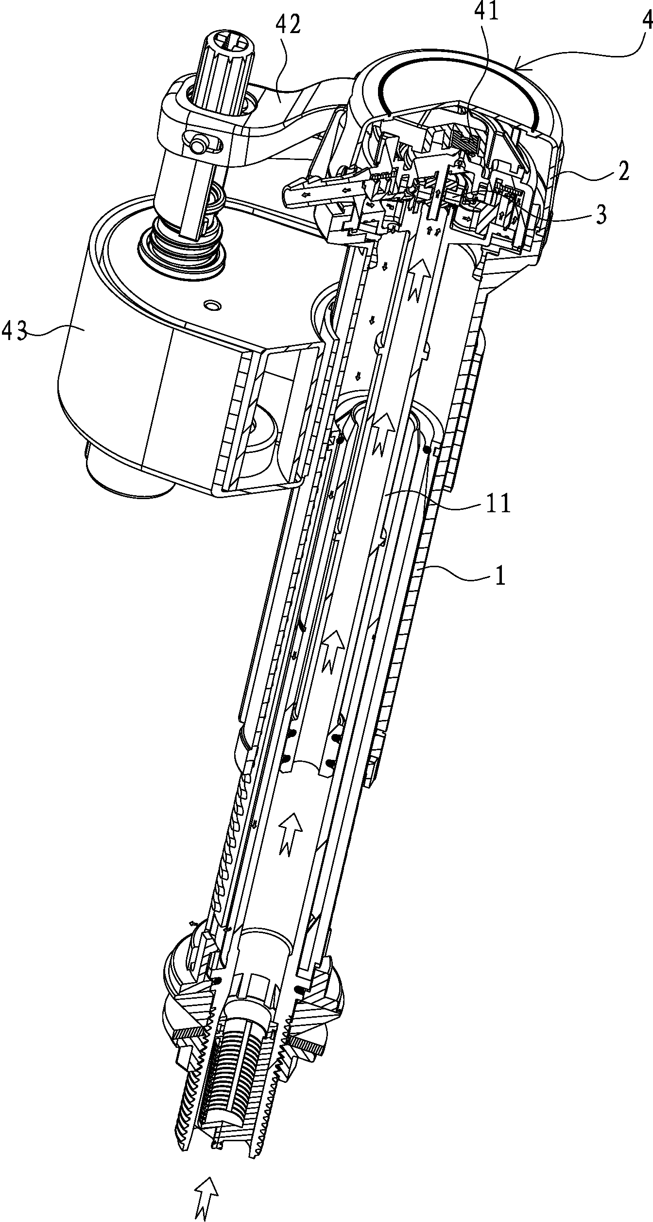
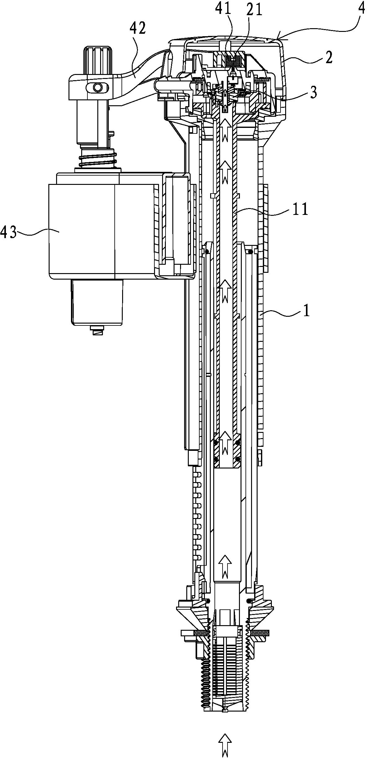
[0047] refer to Figure 1 to Figure 8 As shown, the first embodiment of an anti-siphon structure of a water inlet valve disclosed by the present invention includes a water inlet pipe body 1 , an inner core pipe 11 , a sealing seat 2 , a gasket 3 and a water stop mechanism 4 .

[0048] In this embodiment, the water stop mechanism 4 is composed of a seal seat 2, a seal pad 3, a back pressure pad 41, a swing arm 42 and a buoy 43, that is, the seal pad 3 also functions as a water stop pad, and the seal seat 2 also functions as a water stop pad. The function of the top cover makes the overall structure simpler.

[0049] An air inlet hole (not shown in the figure) is opened on the sealing seat 2, and the sealing seat 2 and the sealing gasket 3 are arranged in cooperation. The sealing seat 2 is installed on the upper end of the water inlet pipe bo...


PUM


Abstract

The invention discloses an anti-siphon structure for a water inlet valve. The anti-siphon structure comprises an inner core pipe, a water inlet pipe, a waterstop mechanism, a sealing gasket and a sealing socket, an air inlet hole is formed in the sealing socket, the sealing socket and the sealing gasket are arranged in a matched manner, the inner core pipe is sleeved in the water inlet pipe, a water inlet channel is formed in the inner core pipe, the waterstop mechanism controls a water outlet of the water inlet channel to open or close, a water outlet channel is formed between the inner core pipe and the water inlet pipe, and a fitting surface is formed on the inner core pipe. When water enters, a water inlet of the inner core pipe is separated from the waterstop mechanism and opened, the sealing gasket and the fitting surface are opened, the air inlet hole in the sealing socket is plugged, so that a transitional channel is formed, and the water inlet channel is communicated with the water outlet channel by the transitional channel. When the water stops entering, the water inlet of the inner core pipe is plugged by the waterstop mechanism and closed, the sealing gasket returns and is fitted with the fitting surface, and an airflow channel is formed between the sealing gasket and the fitting surface. The anti-siphon structure is simple, fine in anti-siphon effect and accurate in CL (center line) marking.

Description

technical field [0001] The invention relates to a water inlet valve, in particular to an anti-siphon structure of the water inlet valve. Background technique [0002] In the prior art, the water inlet valve includes an inner core pipe, a water inlet pipe body, a water stop mechanism, a sealing gasket and a sealing seat; In the water pipe body, a water inlet channel is set in the inner core tube, and the water outlet of the water inlet channel is opened or closed by the water stop mechanism; a water outlet channel is set between the inner core tube and the water inlet pipe body; a sticker is formed on the inner core tube Joint surface, in the state of water intake, the water inlet of the inner core tube is separated from the water stop mechanism, the gasket and the joint surface are opened and the air intake hole on the sealing seat is blocked, thereby forming a transition channel, which will enter The water channel is connected to the water outlet channel, and the water flo...

Claims


Application Information

Patent Timeline
Patent Type & Authority Applications(China)
IPC IPC(8): E03D1/32
Inventor 刘永茂
Owner LAB XIAMEN SANITARY FITTINGS
Learn More