Anti-siphon structure and anti-siphon method of water inlet valve

A technology of anti-siphon and water inlet valve, which is applied in the direction of valve shell structure, flushing equipment with water tank, valve details, etc., can solve the problem of pulling down the CL line, achieve the position of the CL line, simple structure, and improve the anti-siphon effect Effect

Active Publication Date: 2017-03-22
XIAMEN R&T PLUMBING TECH
View PDF1 Cites 0 Cited by
  • Summary
  • Abstract
  • Description
  • Claims
  • Application Information

AI Technical Summary

Problems solved by technology

[0004] The present invention provides an anti-siphon structure and an anti-siphon method of a water inlet valve, which overcomes the disadvantage that the existing anti-siphon structure in the background technology is easy to pull down the CL line

Method used


Image

  • Anti-siphon structure and anti-siphon method of water inlet valve
  • Anti-siphon structure and anti-siphon method of water inlet valve
  • Anti-siphon structure and anti-siphon method of water inlet valve

Examples


Embodiment 1

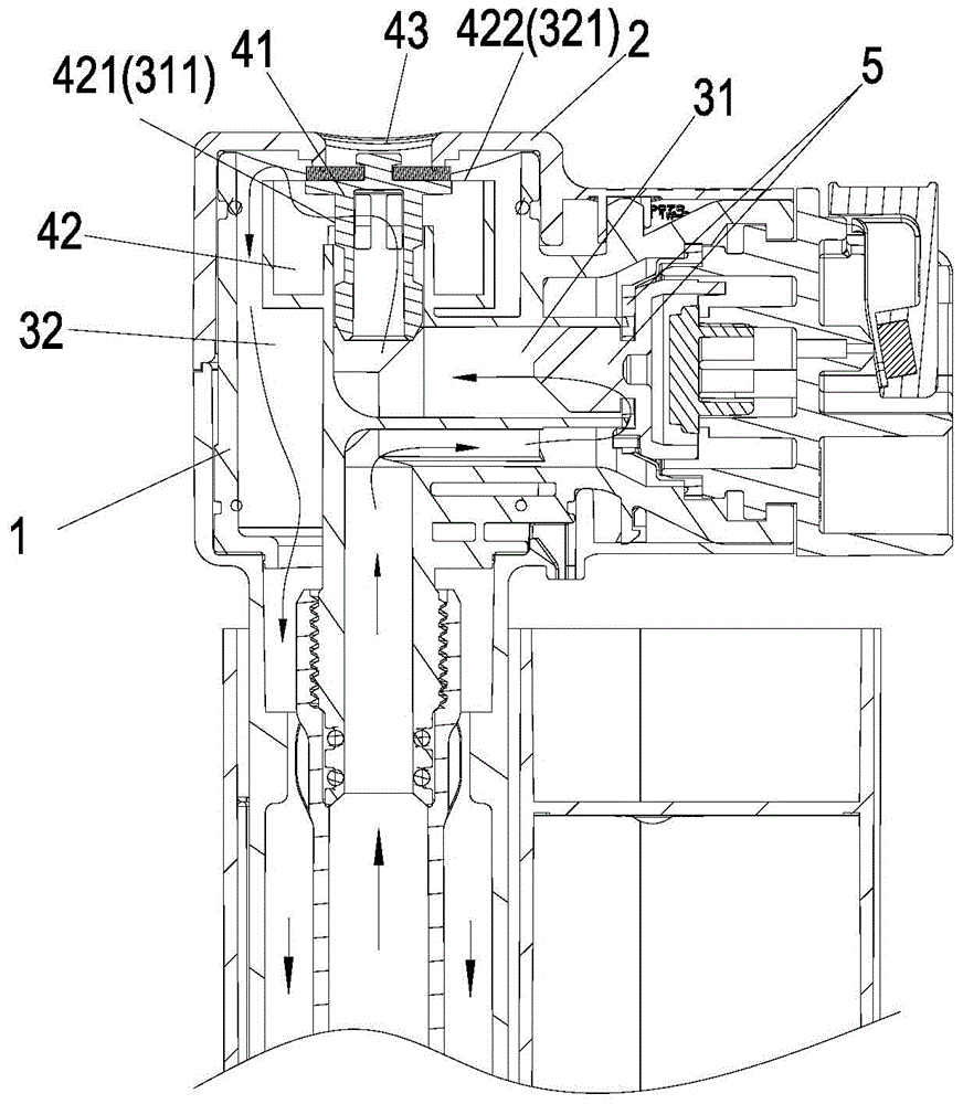
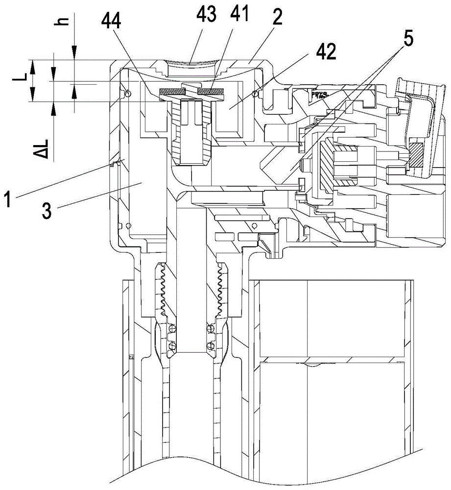
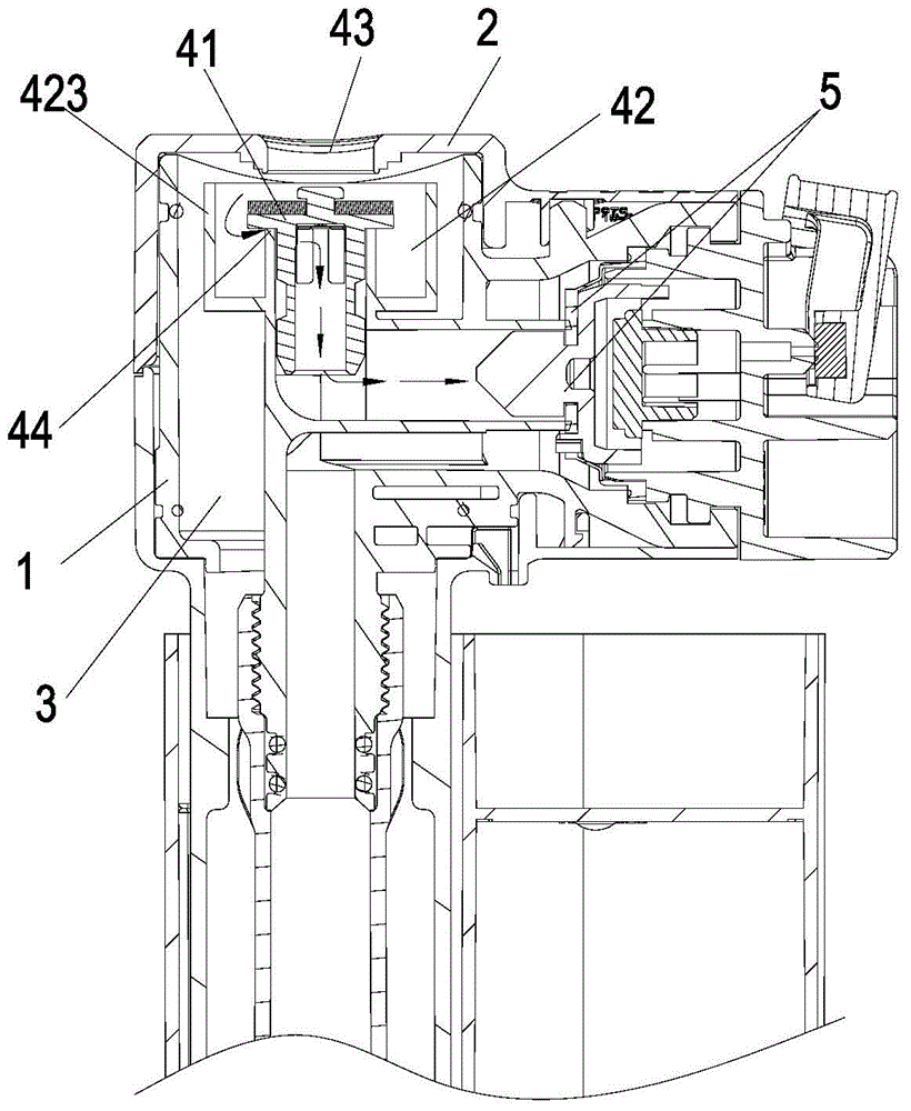
[0034] Please check Figure 1 to Figure 5 , an anti-siphon structure of a water inlet valve, the water inlet valve includes a valve body 1 and a valve cover 2 covered on the valve body 1, the valve body includes a water inlet channel 31 and a water outlet channel 32, the valve body 1 and A valve cavity 3 is formed between the valve covers 2 . In this embodiment, the water inlet valve also includes a water stop component 5 that is movably installed in the valve body 1 and can communicate with or cut off the water inlet channel. In this embodiment, the water stop component 5 is arranged on the side of the top of the valve body 1 .

[0035] The anti-siphon structure includes an air inlet 43 that is located on the top of the valve body 1 and communicates with the inside and outside of the valve body 1. In this implementation, the air inlet 43 is opened on the valve cover 2 at the top of the valve body 1. The air inlet 43 makes the valve cavity 3 connected with the outside air. ...

Embodiment 2

[0044] Please check Figure 7 The difference between this embodiment and Embodiment 1 is that in this embodiment, a notch 3111 is opened at the water outlet end 311 of the water inlet channel 31, and the notch 3111 is used to increase the suction flow area, which can increase the siphon time. Inspiratory volume and increase inspiratory speed.

[0045] Other configurations and working principles of this embodiment are the same as those of Embodiment 1, and will not be repeated here.

Embodiment 3

[0047] Please check Figure 8 and Figure 9 , the difference between this embodiment and Embodiment 1 is:

[0048] A transition channel 33 is included between the water inlet channel 31 and the water outlet channel 32, the transition channel 33 is the isolation chamber 42, and the water inlet end 331 of the transition channel 33 is connected to the water outlet end 311 of the water inlet channel, so The water outlet 332 of the transition channel 33 is connected to the water inlet 321 of the water outlet, and the position of the water outlet 332 of the transition channel is higher than that of the water inlet 331 of the transition channel.

[0049] Other configurations and working principles of this embodiment are the same as those of Embodiment 1, and will not be repeated here.

[0050] The anti-siphon method of a water inlet valve according to the present invention is: an air inlet 43 communicating with the inside and outside of the valve body is provided on the upper part ...


PUM


Abstract

The invention discloses a water inlet valve anti-siphon structure and an anti-siphon method. A water inlet valve comprises a valve body, a water inlet channel, a water outlet channel and a water stop component are arranged in the valve body, and the water stop component is movably connected into the valve body and can communicate or cut off the water inlet channel. The anti-siphon structure comprises an air inlet and an isolation cavity, the air inlet is formed in the upper portion of the valve and communicated with the inside and the outside of the valve body, the isolation cavity is communicated with the air inlet and arranged between a water outlet end of the water inlet channel and a water inlet end of the water outlet channel to spatially isolate the water inlet channel from the water outlet channel, the isolation cavity is provided with a water inlet and a water outlet, the water inlet is communicated with the water inlet channel, the water outlet is communicated with the water outlet channel, and the position of the water outlet is higher than that of the water inlet. As the isolation cavity is formed and the position of the water outlet of the isolation cavity is higher than that of the water inlet, the height of a CL (center line) of the water inlet valve is determined according to the position of the water outlet of the isolation cavity, the position of the CL can be raised, anti-siphon effects are effectively improved, and the anti-siphon structure is simple and low in cost.

Description

technical field [0001] The invention relates to a water inlet valve, in particular to an anti-siphon structure and an anti-siphon method of the water inlet valve. Background technique [0002] When the water is cut off in the tap water pipeline, a negative pressure may be formed in the pipeline, and the water in the water tank will enter the tap water pipeline through the water inlet valve to form a siphon. At present, drinking water and sanitary ware use a set of tap water pipelines, so that Can cause the pollution to drinking water, therefore, the water inlet valve of toilet water tank usually has anti-siphon structure. [0003] In order to increase the CL line of the water inlet valve in the prior art, that is, the critical water level line of the water tank (defined as the lower water level line when the siphon of the water inlet valve starts or ends), most of the anti-siphon structures are made on the water inlet valve. The head, the patent No. ZL200820145319.3 disclos...

Claims


Application Information

Patent Timeline
Patent Type & Authority Patents(China)
IPC IPC(8): F16K27/00F16K15/18E03D1/32
CPCE03D1/32F16K15/18F16K27/00
Inventor 黄贵阳钟志军
Owner XIAMEN R&T PLUMBING TECH
Why Eureka
Try Eureka