Thin-wall whirl central body structure

A swirling center body and thin-walled technology, applied in the field of aero-engine nozzles, can solve the problems of increasing the weight of the nozzle, affecting the range of the throat area of ​​the nozzle, increasing the structural size of the nozzle, etc., and achieving a simple structure and good Stealth function, convenient effect of stealth sawtooth modification

Active Publication Date: 2014-04-02
AECC SHENYANG ENGINE RES INST
View PDF6 Cites 11 Cited by
  • Summary
  • Abstract
  • Description
  • Claims
  • Application Information

AI Technical Summary

Problems solved by technology

[0002] The central body of the traditional aero-engine plug-type axisymmetric nozzle is a closed structure. Although the nozzle has a good stealth function, this structure has a large cross-sectional area, but it seriously affects the throat area of ​​the nozzle. Range, in order to ensure the normal throat adjustment range, the aero-engine needs to increase the structural size of the nozzle, resulting in an increase in the weight of the nozzle; while the traditional aero-engine axisymmetric nozzle has no shielding structure for the front-end hot-end parts in the middle , greatly reducing its stealth ability

Method used


Image

  • Thin-wall whirl central body structure
  • Thin-wall whirl central body structure
  • Thin-wall whirl central body structure

Examples


Embodiment 1

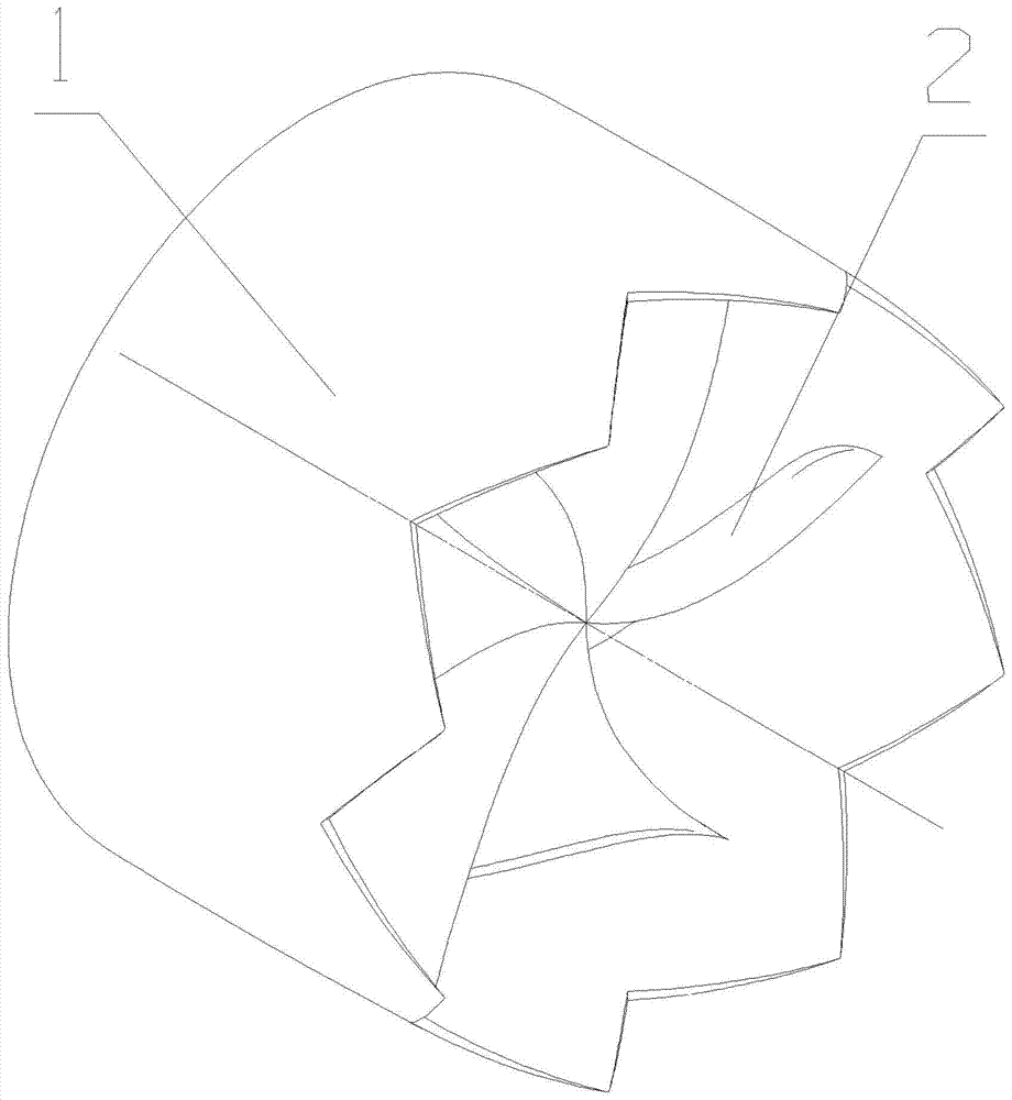
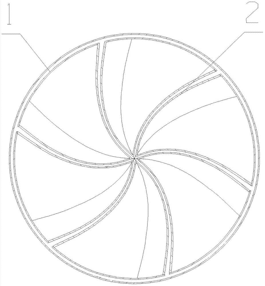
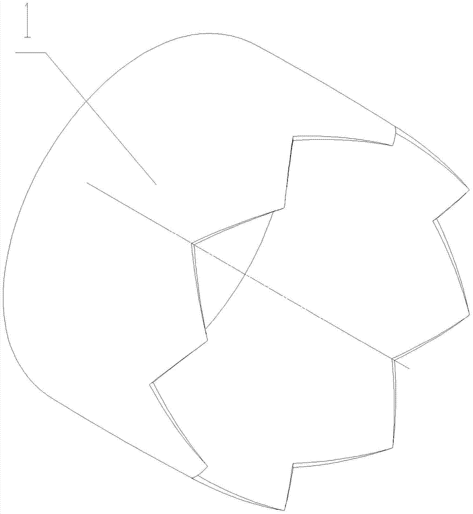
[0029] A thin-wall swirl center body structure mainly consists of a thin-wall annular structure 1 and a thin-wall swirl leaf-shaped structure 2 . Specifically:

[0030] The thin-walled annular structure 1 is located on the outside, and is connected with the cylinder of the axisymmetric nozzle through a supporting member, and is used to fix the thin-walled swirl leaf-shaped structure 2, and at the same time, change the flow direction of the airflow flowing through the thin-walled swirl leaf-shaped structure 2 back along the axis of the nozzle. direction.

[0031] The thin-walled swirling leaf-shaped structure 2 is located in the front middle section of the inner side of the thin-walled annular structure 1, arranged along the circumferential direction of the thin-walled annular structure 1, and is fixedly connected with the thin-walled annular structure 1. The front section and the rear section form a certain angle in the circumferential direction, so that The thin-walled swirl...

Embodiment 2

[0043] A thin-wall swirl center body structure mainly consists of a thin-wall annular structure 1 and a thin-wall swirl leaf-shaped structure 2 . Specifically:

[0044] The thin-walled annular structure 1 is located on the outside, and is connected with the cylinder of the axisymmetric nozzle through a supporting member, and is used to fix the thin-walled swirl leaf-shaped structure 2, and at the same time, change the flow direction of the airflow flowing through the thin-walled swirl leaf-shaped structure 2 back along the axis of the nozzle. direction.

[0045] The thin-walled swirling leaf-shaped structure 2 is located in the front middle section of the inner side of the thin-walled annular structure 1, arranged along the circumferential direction of the thin-walled annular structure 1, and is fixedly connected with the thin-walled annular structure 1. The front section and the rear section form a certain angle in the circumferential direction, so that The thin-walled swirl...

Embodiment 3

[0057] A thin-wall swirl center body structure mainly consists of a thin-wall annular structure 1 and a thin-wall swirl leaf-shaped structure 2 . Specifically:

[0058] The thin-walled annular structure 1 is located on the outside, and is connected with the cylinder of the axisymmetric nozzle through a supporting member, and is used to fix the thin-walled swirl leaf-shaped structure 2, and at the same time, change the flow direction of the airflow flowing through the thin-walled swirl leaf-shaped structure 2 back along the nozzle axis. direction.

[0059] The thin-walled swirl leaf-shaped structure 2 is located in the front middle section of the inner side of the thin-walled annular structure 1, arranged along the circumferential direction of the thin-walled annular structure 1, and fixedly connected with the thin-walled annular structure 1, and the front section and the rear section form a certain angle in the circumferential direction, so that The thin-walled swirling leaf-...


PUM


Abstract

The invention provides a thin-wall whirl central body structure which consists of a thin-wall annular structure and a thin-wall whirl blade-shaped structure and is characterized in that the thin-wall annular structure is positioned at the outside, connected with a cylinder of an axially symmetrical nozzle by virtue of a support member and used for fixing the thin-wall whirl blade-shaped structure and meanwhile changing the flow direction of airflow flowing through the thin-wall whirl blade-shaped structure into a direction along the axial direction of the nozzle; the thin-wall whirl blade-shaped structure is positioned at a front middle section inside the thin-wall annular structure, arranged along the circumferential direction of the thin-wall annular structure and fixedly connected with the thin-wall annular structure; the sections of the front and rear ends of the thin-wall whirl blade-shaped structure form a certain angle in the circumferential direction, so that the thin-wall whirl blade-shaped structure can shield a hot end member at the front end of the engine, and a hiding function is achieved. The thin-wall whirl central body structure has the following advantages that the regulation range of the throat area of a traditional axially-symmetrical plug nozzle is not influenced; the thin-wall whirl central body structure can be applied to other types of traditional axially-symmetrical nozzles, so that a favorable hiding function is achieved, the structure is simple, and hidden sawtooth shaping can be performed conveniently.

Description

technical field [0001] The invention belongs to the field of aero-engine nozzles, and relates to a thin-wall swirl center body structure, which is suitable for axisymmetric plug nozzles and other types of axisymmetric nozzles. Background technique [0002] The central body of the traditional aero-engine plug-type axisymmetric nozzle is a closed structure. Although the nozzle has a good stealth function, this structure has a large cross-sectional area, but it seriously affects the throat area of ​​the nozzle. Range, in order to ensure the normal throat adjustment range, the aero-engine needs to increase the structural size of the nozzle, resulting in an increase in the weight of the nozzle; while the traditional aero-engine axisymmetric nozzle has no shielding structure for the front-end hot-end parts in the middle , greatly reducing its stealth ability. Therefore, in order to overcome the defects of the center body of the traditional aero-engine plug-type axisymmetric nozzl...

Claims


Application Information

Patent Timeline
Patent Type & Authority Applications(China)
IPC IPC(8): F02K1/78
Inventor 赵春生
Owner AECC SHENYANG ENGINE RES INST
Why Eureka
Try Eureka