Quadraphonic ultrasonic heat meter

An ultrasonic and heat meter technology, applied in the field of four-channel ultrasonic heat meters, can solve problems such as unsuitable fluid flow, flow velocity distribution distortion, poor adaptability, etc., to reduce the difficulty of correction, reduce installation requirements, and improve adaptability Effect

Inactive Publication Date: 2014-04-02
RUINA INTELLIGENT EQUIP CO LTD
View PDF5 Cites 9 Cited by
  • Summary
  • Abstract
  • Description
  • Claims
  • Application Information

AI Technical Summary

Problems solved by technology

[0002] Common multi-channel sound channel arrangement is relatively simple, evenly distributed in parallel or distributed along the circumference and concentrated to cross to a point on the axis, that is, the section of the circular tube is equally divided in the diameter direction, and the distance between the channels is DN / ( n+1), this arrangement does not conform to the characteristics of fluid flow, and it has poor adaptability to occasions where the installation environment is not good, especially when there are many elbows, valves and other resistance parts in the upstream, the measurement chamber The flow velocity distribution is distorted, resulting in a significant drop in measurement accuracy, and the effect is not good

Method used


Image

  • Quadraphonic ultrasonic heat meter
  • Quadraphonic ultrasonic heat meter
  • Quadraphonic ultrasonic heat meter

Examples


specific Embodiment approach

[0014] Four-channel ultrasonic heat meter of the present invention, its preferred embodiment is:

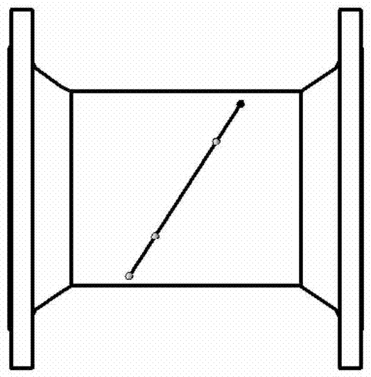
[0015] Including the pipe body, the wall of the pipe body is provided with eight installation ports, and each installation port is respectively equipped with an ultrasonic transducer, and the eight ultrasonic transducers are opposite to each other to form a sound channel, and among the four sound channels The axes of every two sound channels are parallel to each other, have the same length and are symmetrically distributed on both sides of the axis of the tube body, and the distances between the axes of the two sound channels and the axis of the tube body are equal.

[0016] Viewed from the end face of the tube body, each transducer protrudes 1 / 3-1 / 4 of the inner cavity of the pipeline.

[0017] A transducer mounting seat is welded on the pipe body at the installation port, and the ultrasonic transducer is coaxially installed with the transducer mounting seat.

[0018] Both ends...

specific Embodiment

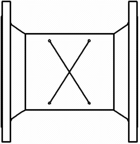
[0030] Such as Figure 1a to Figure 3b As shown, eight oblique holes are precisely machined on the pipe body, two of which are coaxial; based on the oblique holes, eight transducer mounting seats are welded on the steel pipe; then the flanges are welded on both ends of the pipe body; The ultrasonic transducer assembly is put into it, and the transducer gland is covered.

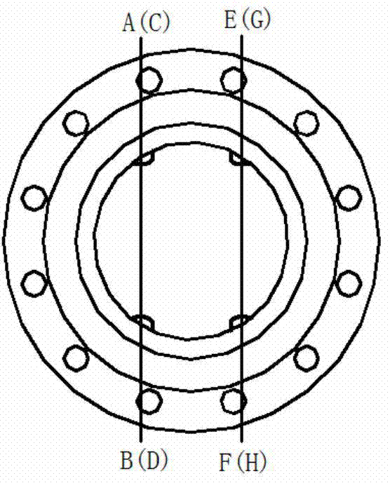
[0031] Viewed from the end face of the tube, A transducer is coaxial and opposite to B transducer, C transducer is coaxial and opposite to D transducer; E transducer is coaxial and opposite to F transducer , the G transducer and the H transducer are coaxial and opposite; the signals of the four channels are independent of each other and are in the required position.

[0032] Working process: A transducer, C transducer, E transducer, G transducer can transmit ultrasonic signals at the same time, or send and transmit ultrasonic signals in time-sharing; B transducer, D transducer, F transducer , The G transduc...

Embodiment 1

[0036] Such as Figure 1a , 1b As shown, the distance between the channel and the axis of the pipe body is equal to the value of the two channels, the AB channel and the CD channel are on the same plane and cross, the EF channel and the GH channel are on the same plane and cross, the structure is the most Simple.


PUM


Abstract

The invention discloses a quadraphonic ultrasonic heat meter. The meter comprises a pipe body, wherein the wall of the pipe body is provided with eight mounting ports, each mounting port is respectively provided with an ultrasonic transducer, four sound tracks are formed by the eight ultrasonic transducers which are opposite in pairs, the axes of every two sound tracks in the four tracks are parallel to each other, are equal in length and are symmetrically distributed at the two sides of the axis of the pipe body, and the distances between the axes of the two sound tracks and the axis of the pipe body are equal. The transducers are distributed on a section according with the velocity distribution rule of a flow field, so that the correction difficulty of measuring errors caused by a computing instrument matched with a flowmeter can be greatly reduced, and a final measuring result is more accurate; the adaptability and the stability of the ultrasonic heat meter on different incoming flows can be improved, and the installation requirements can be reduced.

Description

technical field [0001] The invention relates to an ultrasonic heat meter, in particular to a four-channel ultrasonic heat meter. Background technique [0002] Common multi-channel sound channel arrangement is relatively simple, evenly distributed in parallel or distributed along the circumference and concentrated to cross to a point on the axis, that is, the section of the circular tube is equally divided in the diameter direction, and the distance between the channels is DN / ( n+1), this arrangement does not conform to the characteristics of fluid flow, and it has poor adaptability to occasions where the installation environment is not good, especially when there are many elbows, valves and other resistance parts in the upstream, the measurement chamber The flow velocity distribution is distorted, resulting in a significant drop in measurement accuracy, and the effect is not good. Contents of the invention [0003] The purpose of the present invention is to provide a four...

Claims


Application Information

Patent Timeline
Patent Type & Authority Applications(China)
IPC IPC(8): G01K17/06G01F1/66G01P5/24
Inventor 巫军华王兆杰
Owner RUINA INTELLIGENT EQUIP CO LTD
Why Eureka
Try Eureka