Polyurethane foam

A polyurethane foam and foam technology, applied in the field of polyurethane foam, can solve problems such as voids and unpractical sealing materials, and achieve the effect of small compressive residual strain

Active Publication Date: 2014-04-02
INOAC CORP +1
View PDF5 Cites 9 Cited by
  • Summary
  • Abstract
  • Description
  • Claims
  • Application Information

AI Technical Summary

Problems solved by technology

Therefore, in the case where the compound is added in a large amount to the polyurethane raw material, there is a possibility that defects such as voids (also called pinholes) are generated in the polyurethane foam in the mechanical foaming method
Furthermore, even in either of (1) and (2), the obtained polyurethane foam may have high hardness, and as a result, such polyurethane foam is not practical as a sealing material

Method used


Image

  • Polyurethane foam
  • Polyurethane foam
  • Polyurethane foam

Examples


Embodiment

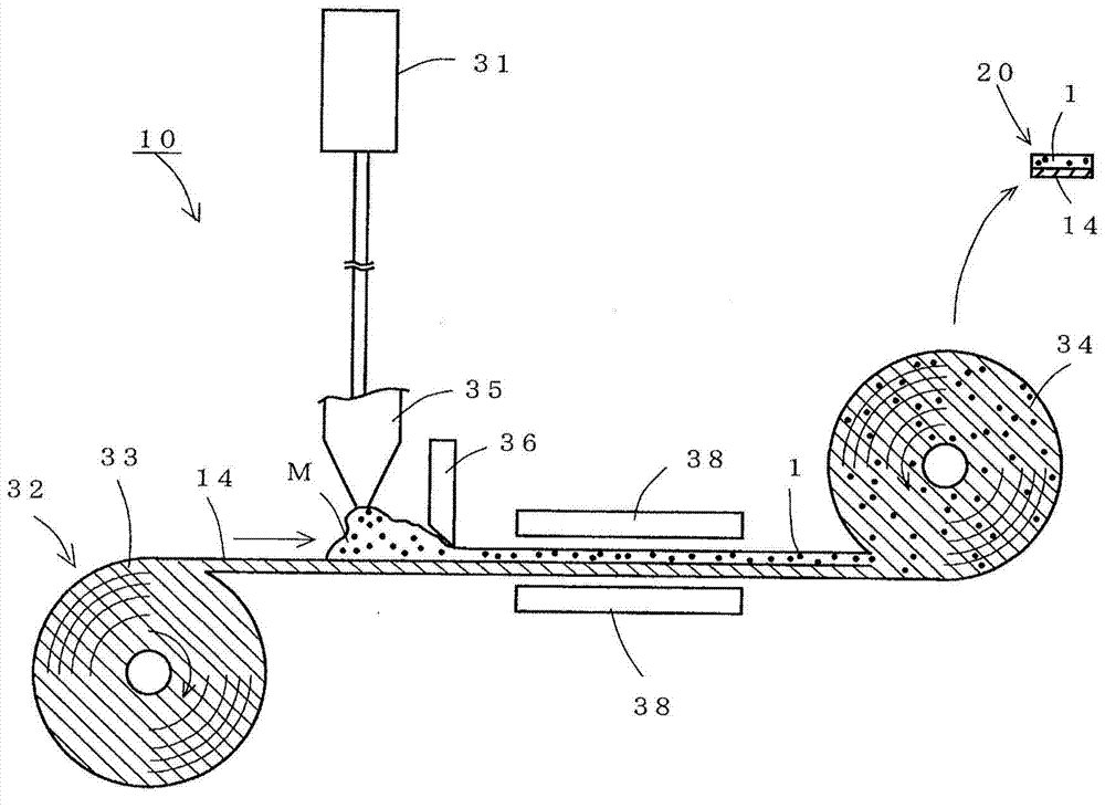
[0080] use figure 2 The production apparatus 10 shown in , produced the polyurethane foam 1 of Examples 1-15 from the polyurethane raw material M having the formulation shown in Tables 1 and 2. In this case, a PET film having a thickness of 25 to 125 μm is used as the base material 14 , and the polyurethane raw material is heated to 120 to 200° C. by heating means 38 . Nitrogen as a gas for foam formation was supplied into the mixing section 31 at a flow rate of 0.1 NL / min and mixed with the polyurethane raw material so as to achieve the mixing ratios (volume %) in Tables 1 and 2. The feeding speed of the substrate 14 in the roller mechanism 32 was 5 m / min.

[0081] For comparison, polyurethane foams of Comparative Examples 1 to 10 were obtained from polyurethane raw materials having the formulations shown in Table 3. In Comparative Examples 1 to 7, the polyurethane foam was produced by the same production method as in Examples 1 to 14, but the formulation of the polyuretha...


PUM

PropertyMeasurementUnit
viscosityaaaaaaaaaa
densityaaaaaaaaaa
thicknessaaaaaaaaaa

Abstract

In the present invention, a polyurethane foam (1) is obtained by the mechanical floss method from a polyurethane starting material comprising a polyol, isocyanate, foam stabilizer, catalyst and a gas for foaming, wherein the polyol comprises a castor oil-based polyol and a polyether-based polyol having a viscosity of 2,000 mPas or lower at 25 C; the castor-oil based polyol accounts for between 20 and 80 parts by weight of the 100 parts by weight of the polyol; the polyether polyol accounts for between 20 and 80 parts by weight of the 100 parts by weight of the polyol; apparent density is between 100 and 700 kg / m3; and compressive residual strain at 100 C is 20% or lower. This polyurethane foam is ideal as a material for sealing peripheral regions of a heat source.

Description

technical field [0001] The present invention relates to a polyurethane foam. Background technique [0002] Conventionally, silicone foam or rubber sponge is used as a sealing material for the periphery of a heat source portion such as the battery periphery of an electric vehicle or the periphery of an electronic control portion, or for a sealing portion of a solar cell. [0003] However, it is difficult to form a sealing material containing silicone foam to a thickness of less than 0.8 mm. Therefore, the sealing material comprising silicone foam has a large thickness and cannot be used in areas where a thin sealing material is required. In addition, raw material costs are high, and products cannot be provided at low prices. [0004] On the other hand, rubber sponges have large compressive residual strains and thus have low long-term sealing properties. In addition, there is a possibility that the sulfur-containing gas generated by the rubber sponge corrodes the electronic...

Claims


Application Information

Patent Timeline
Patent Type & Authority Applications(China)
IPC IPC(8): C08G18/42C08G101/00
CPCC08J9/122C08G18/6696C08G2350/00C08G18/44C08G2101/0066C08G18/4018C08G18/6629C08G18/36C08G18/4244C08G18/3206C08G2101/00C08J2375/08C08J9/02C08J2203/06C08J2205/044C08J2205/06C08J2375/04C08G2110/0066
Inventor 小柳津诚司
Owner INOAC CORP
Why Eureka
Try Eureka