Antenna control method and antenna apparatus using the same

An antenna control method and an antenna device technology, which are applied to antennas, use feedback control, electrical components, etc., and can solve problems such as rough adjustment, time-consuming, and inconvenience

Active Publication Date: 2014-04-09
WISTRON NEWEB
View PDF5 Cites 4 Cited by
  • Summary
  • Abstract
  • Description
  • Claims
  • Application Information

AI Technical Summary

Problems solved by technology

This method is not only time-consuming and inconvenient, but also because it is manual and rough adj

Method used


Image

  • Antenna control method and antenna apparatus using the same
  • Antenna control method and antenna apparatus using the same
  • Antenna control method and antenna apparatus using the same

Examples


Embodiment Construction

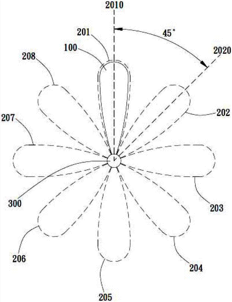
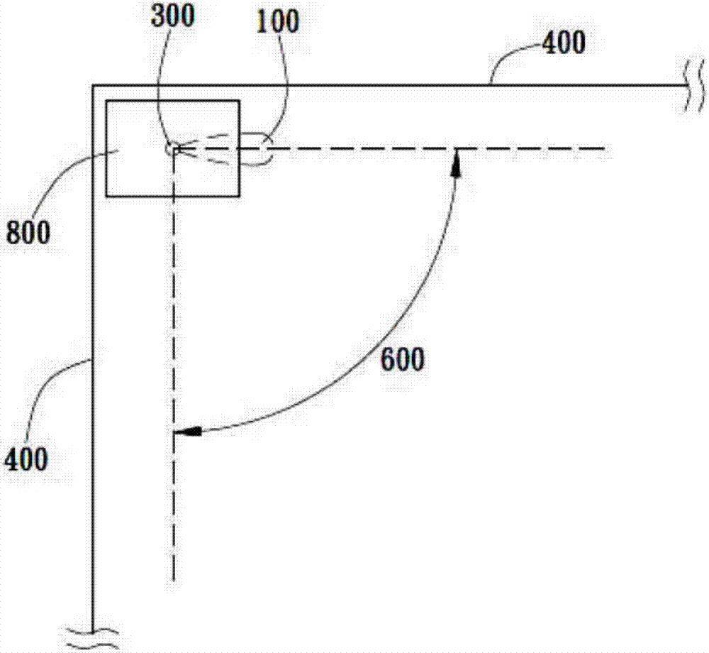
[0034] The antenna control method of the present invention is used for an antenna, wherein the antenna can be rotated in the signal area. Specifically, as figure 1 In the preferred embodiment shown, the signal area includes a 360° full-circle angle area on the same plane, and one end of the antenna 100 is connected to the rotary driving device 300 so as to rotate 360° in the signal area. However, in different embodiments, the signal area is not limited to the same plane, nor is it limited to a 360° full-circle angle area. For example in figure 2 In the illustrated embodiment, the antenna device 800 with the antenna 100 is disposed at a corner between two walls 400 . In this case, the signal area may be a 90° angle area 600 on the same plane.

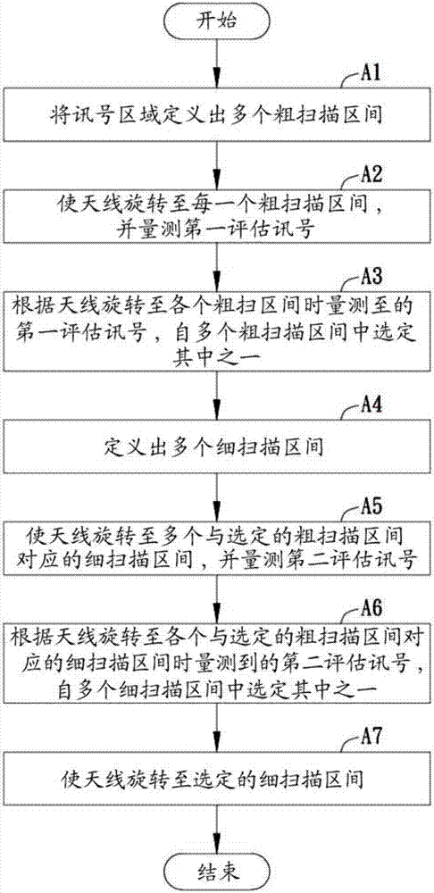
[0035] Such as image 3 In the flow chart of the embodiment shown, the antenna control method of the present invention includes, for example, the following steps.

[0036] In step (A1), the signal area is defined into a plurality o...


PUM


Abstract

The invention relates to an antenna control method and an antenna apparatus using the same. The method comprises the following steps: (A1), defining a signal zone to obtain a plurality of coarse scanning intervals; (A2), enabling an antenna to rotate to each coarse scanning interval and measuring a first evaluation signal; (A3), according to the first evaluation signal that is measured during antenna rotation to all the coarse scanning intervals, selecting one coarse scanning interval from the plurality of coarse scanning intervals; (A4), obtaining a plurality of fine scanning intervals by defining; (A5), enabling the antenna to rotate to the plurality of fine scanning intervals corresponding to the selected coarse scanning interval and measuring a second evaluation signal; (A6), according to the second evaluation signal that is measured during the antenna rotation to all the fine scanning intervals corresponding to the selected coarse scanning intervals, selecting one fine scanning interval from the plurality of fine scanning intervals; and (A7), enabling the antenna to rotate to the selected fine scanning interval.

Description

technical field [0001] The present invention relates to an antenna control method for an antenna and an antenna device using the antenna control method. Background technique [0002] With the advancement of electronic technology and the popularization of computer applications, various portable electronic products have been widely used in daily life. Among them, in order to facilitate the connection of portable electronic products with the network, improve the signal transmission and reception effect to provide good video call and network communication quality, the types and designs of the signal transmission and reception antennas of the network base station are getting more and more attention. [0003] Rotating antennas are widely used because they can be rotated to adjust the angle of the antenna, so as to direct the antenna towards a better signal receiving and receiving angle, such as stronger signal or less noise, and improve the signal receiving and receiving effect. ...

Claims


Application Information

Patent Timeline
IPC IPC(8): H01Q3/08G05D3/12
Inventor 方振鸿黄智威林玟君
Owner WISTRON NEWEB
Why Eureka
Try Eureka