Control device and pneumatic system

A control device and control valve technology, applied in valve device, valve operation/release device, valve details, etc., can solve the problem of high overall cost, avoid the setting of control lines, reduce the use of coils, and reduce costs. Effect

Active Publication Date: 2014-04-16
CHINA RESOURCES POWER HENAN SHOUYANGSHAN
View PDF6 Cites 2 Cited by
  • Summary
  • Abstract
  • Description
  • Claims
  • Application Information

AI Technical Summary

Problems solved by technology

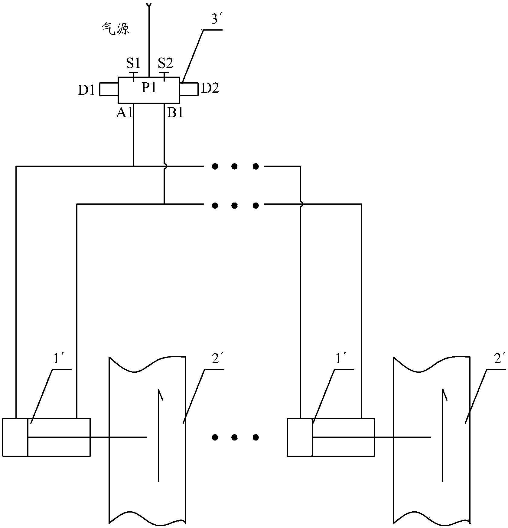
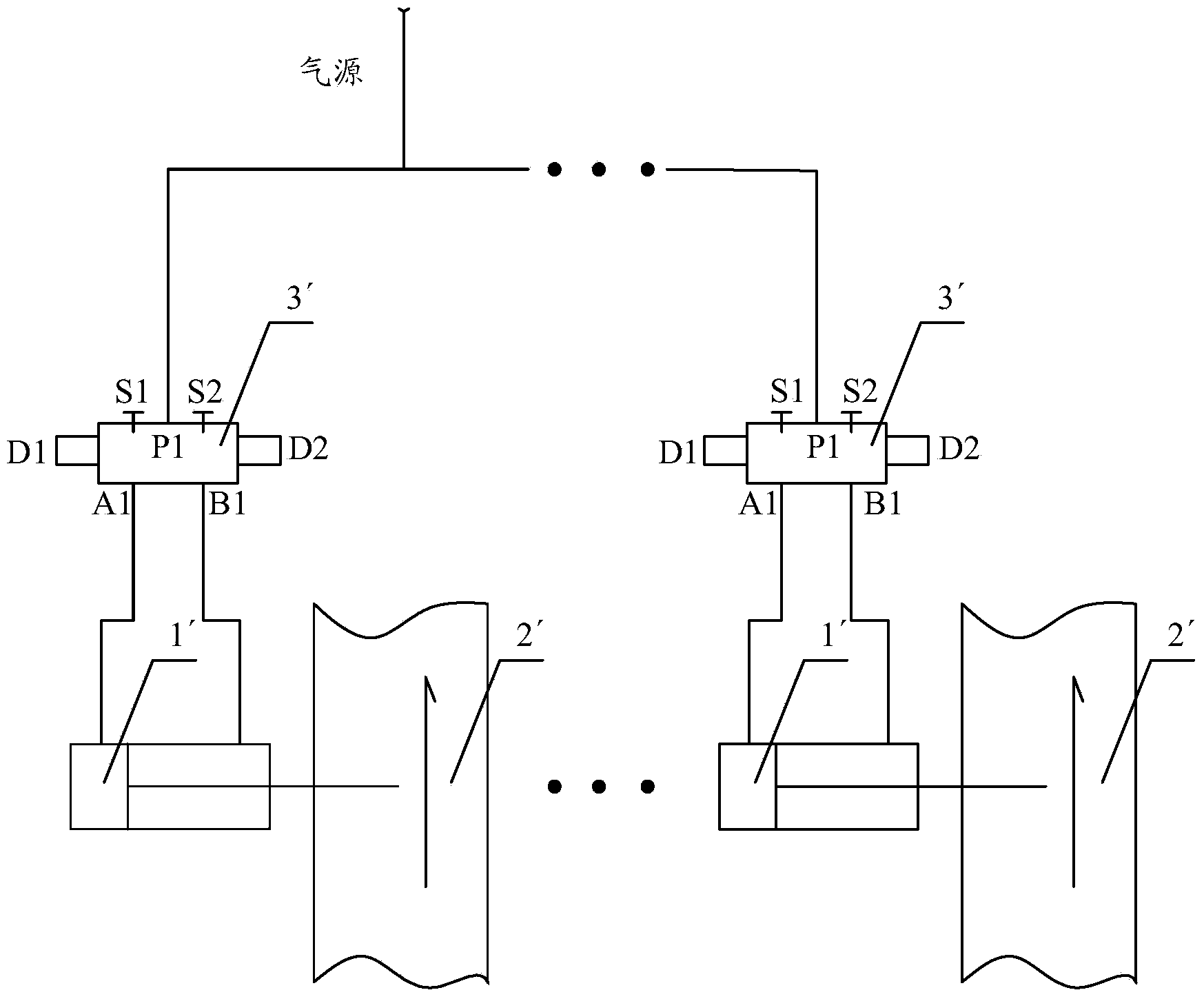
However, this design needs to control the 2′ coils of each valve. If the solenoid valve, gas source pipeline, and cable costs are calculated, the control cost of each valve is about 5,000 yuan or more. If there are many valves or locations far, the overall cost will be very expensive

Method used


Image

  • Control device and pneumatic system
  • Control device and pneumatic system
  • Control device and pneumatic system

Examples


Embodiment Construction

[0029] The core of the invention is to disclose a control device to achieve the purpose of reducing costs. Hereinafter, an embodiment will be described with reference to the drawings. In addition, the examples shown below do not limit the content of the invention described in the claims in any way. In addition, all the contents of the configurations shown in the following embodiments are not limited to be essential to the solutions of the invention described in the claims.

[0030] Such as Figure 4 As shown, the control device includes a control valve 3 and a plurality of pneumatic valves, and also includes a plurality of manual switching valves 4, the third interface A2 of the manual switching valve 4 communicates with the air inlet of the cylinder 1 of the pneumatic valve, and manually The fourth port B2 of the switching valve 4 communicates with the air outlet of the cylinder 1 of the pneumatic valve, the first port P2 of multiple manual switching valves 4 communicates w...


PUM


Abstract

The embodiment of the invention discloses a control device. A manual changeover valve is additionally arranged between a control valve and air cylinders of a plurality of pneumatic valves, secondary changeover can be conducted to air ways of the air cylinders of the plurality of pneumatic valves through the manual changeover valve in the on state of the pneumatic valve so as to realize the simultaneous control on the air cylinders of the plurality of pneumatic valves, one or more valves can be separately switched off without the need of switching off all the valves or stopping a system when a part of technological pipeline does not work. Compared with the prior art, according to the control device, the manual changeover valve is not required from being additionally arranged and electromagnetic valves are not separately used, so that the arrangement of a control line using a control coil to work can be avoided while the usage amount of coils can be reduced, therefore the cost can be lowered. The embodiment of the invention further discloses a pneumatic system.

Description

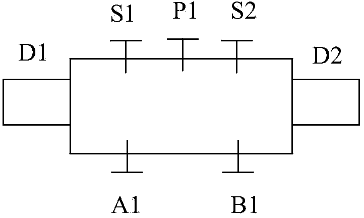
technical field [0001] The invention relates to the technical field of boilers, more specifically, to a control device and a pneumatic system. Background technique [0002] For large-scale process systems, due to the complexity of the process, it is necessary to set pneumatic valves on the pipeline 2' to control the fluid in them. Some of the valves need to be opened or closed at the same time when the system is running. Among them, the pneumatic valve is closed separately to cut off the fluid in it. The commonly used control element for pneumatic valves is the two-position five-way solenoid valve 3', such as figure 1 As shown, the two-position five-way solenoid valve 3' has two coils in total. When the coils are charged respectively, the switching of the gas circuit can be controlled, so that the cylinder 1' driving the pneumatic valve can supply or exhaust air, so as to realize the opening or closing of the pneumatic valve. valve. When the coil D1 is electrified, the ai...

Claims


Application Information

Patent Timeline
Patent Type & Authority Applications(China)
IPC IPC(8): F16K31/14
CPCF16K31/14
Inventor 赵寒冰
Owner CHINA RESOURCES POWER HENAN SHOUYANGSHAN
Why Eureka
Try Eureka