An ultra-low temperature loading and unloading arm structure with overflow prevention pipeline

An ultra-low temperature, loading and unloading arm technology, used in packaging, distribution devices, transportation and packaging, etc., can solve the problems of the loading and unloading arm lack of overflow prevention system, unable to achieve low temperature sealing requirements, safety hazards and other problems, to solve the problem of uneven deformation of the sealing surface, The effect of solving low temperature sealing problems and eliminating safety hazards

Inactive Publication Date: 2017-04-26
SHANGHAI EMINENT ENTERPRISE DEV
View PDF4 Cites 0 Cited by
  • Summary
  • Abstract
  • Description
  • Claims
  • Application Information

AI Technical Summary

Problems solved by technology

[0002] The various parts of the rotary joint of the low-temperature crane tube shrink under low-temperature working conditions, and the sealing surfaces of many structures are deformed unevenly, and the sealing structure cannot be guaranteed, so the low-temperature sealing requirements cannot be achieved; at the same time, during the entire loading and unloading process, the air The moisture will freeze in the raceway and damage the raceway, resulting in inflexible rotation of the rotary joint
In addition, the existing loading and unloading arm lacks an overflow prevention system, especially for the hydraulic control part on the periphery of the inner arm, that is, the end that is easy to repair, and when the fluid material is delivered to the tank, the delivery pipeline cannot be automatically closed when the tank is filled with fluid The valves on the tank often cause fluid overflow, especially when transporting fuel oil and chemicals, which poses a great safety hazard; at the same time, the anti-overflow control of three-dimensional joints also needs to be strengthened

Method used


Image

  • An ultra-low temperature loading and unloading arm structure with overflow prevention pipeline
  • An ultra-low temperature loading and unloading arm structure with overflow prevention pipeline

Examples


Embodiment Construction

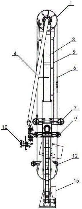
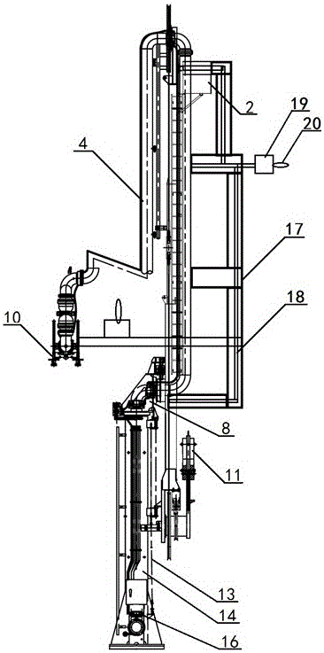
[0017] like Figure 1-2 As shown, the ultra-low temperature loading and unloading arm structure with overflow prevention pipeline described in the embodiment of the present invention includes the upper sheave and the outer arm support assembly 1, the trunnion box 8, the column 14 and the nitrogen purging device 16, and the column 14 The upper and lower ends are respectively installed with the upper sheave and the outer arm support assembly 1, and the nitrogen purge device 16, which is located at the center of the upper sheave and the outer arm support assembly 1 and is connected to the outwardly extending process pipeline 4, and the process pipeline 4 is A three-dimensional joint 10 is installed at the end of the three-dimensional joint 10, and an emergency release device is provided on the surface of the three-dimensional joint 10; a support box 3 is arranged between the upper sheave and the outer arm support assembly 1 and the column 14, and the upper sheave and the outer arm...


PUM


Abstract

The invention relates to an ultralow temperature loading arm structure with an anti-overflowing pipeline. The ultralow temperature loading arm structure comprises an upper rope wheel and outer arm supporting assembly, a trunnion box, an upright post and a nitrogen purging device, wherein the upper rope wheel and outer arm supporting assembly and the nitrogen purging device are respectively arranged at the upper end and the lower end of the upright post; a process pipeline extending outwards is positioned at the central position of the upper rope wheel and outer arm supporting assembly in a connecting manner, and a three-dimensional joint is arranged at the outer end of the process pipeline; meanwhile, an inner arm driving mechanism is arranged on the middle section of the upright post, an outer arm driving mechanism is arranged at the lower part of the upright post, a horizontal driving mechanism is arranged between the inner am driving mechanism and the outer arm driving mechanism, and an electric hydraulic control unit is arranged at the bottom of the upright post. The ultralow temperature loading arm structure has the beneficial effects that electric hydraulic control of global and local mechanisms can be realized; the operation flexibility of inner and outer arms is improved; meanwhile, the ultralow temperature loading arm structure is provided with the nitrogen purging mechanism, so that the problem that the deformation of sealing surfaces is non-uniform under a low temperature is effectively solved.

Description

technical field [0001] The invention relates to fluid loading and unloading equipment, in particular to an ultra-low temperature loading and unloading arm structure with an overflow prevention pipeline. Background technique [0002] The various parts of the rotary joint of the low-temperature crane tube shrink under low-temperature working conditions, and the sealing surfaces of many structures are deformed unevenly, and the sealing structure cannot be guaranteed, so the low-temperature sealing requirements cannot be achieved; at the same time, during the entire loading and unloading process, the air The excess moisture will freeze in the raceway and damage the raceway, resulting in inflexible rotation of the rotary joint. In addition, the existing loading and unloading arm lacks an overflow prevention system, especially for the hydraulic control part on the periphery of the inner arm, that is, the end that is easy to repair, and when the fluid material is delivered to the t...

Claims


Application Information

Patent Timeline
Patent Type & Authority Patents(China)
IPC IPC(8): B67D7/06B67D9/00
Inventor 盛立新
Owner SHANGHAI EMINENT ENTERPRISE DEV
Why Eureka
Try Eureka